Did you know KiCad has a SPICE simulator?
Sometimes I notice the “Simulator” tab in KiCad, and I think about if it is actually any good. So I did some research into how it works and how to use it!
KiCad uses ngspice, which is a SPICE simulator designed with command-line or file input in mind. Subsequently, it does not come with a graphical user interface. Instead, KiCad provides the schematic editor as a user interface, and converts the connected components and parameters into a format ngspice can use. At a high level, it works basically the same as LTspice and other popular SPICE programs. You place down special components that have adjustable parameters, and pick a certain simulation type to run (DC operating point, AC analysis, transient analysis, etc). You can open the simulator tab from the schematic editor as seen here:
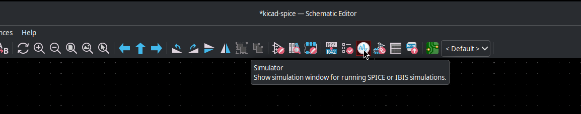
The Simulator icon in the main toolbar at the top (looks like a waveform on an oscilloscope).
When you open it, this is what you will see initially:
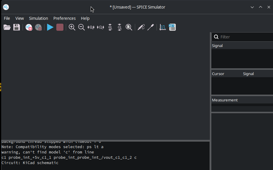
The initial window of the SPICE simulator.
So, to demonstrate how it works, I built this very simple circuit with the intent of performing a transient analysis:
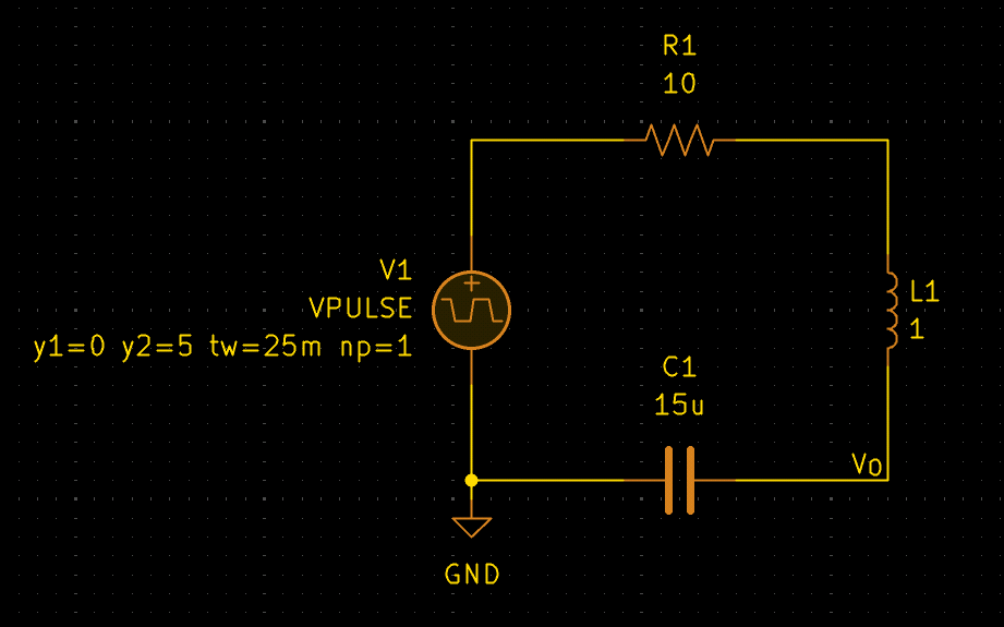
The basic RLC circuit I made with a 5V pulse input that lasts for 25ms. The node to the right of C1 has a net label of “VO” so I can easily see it in the simulator.
You can find all the SPICE simulation specific components if you search for “SPICE” in the place symbols menu. I used a VPULSE component, which is an adjustable voltage pulse source. If you need to quickly find out how to use these SPICE specific symbols and what parameters you can use, you can select them and press “D” which will open the documentation for it (this works for other symbols too with a link in the “documentation” symbol field!). In my case, I just wanted a 25ms 5V pulse, so I opened the documentation for it and saw these parameters and tweaked them as I needed:
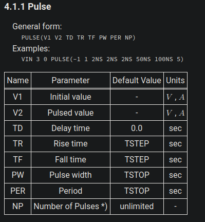
The list of parameters for the VPULSE SPICE component.
Now, I just needed to set the simulator up with the right simulation parameters. You’re going to want to add a new “Analysis Tab” as seen here:
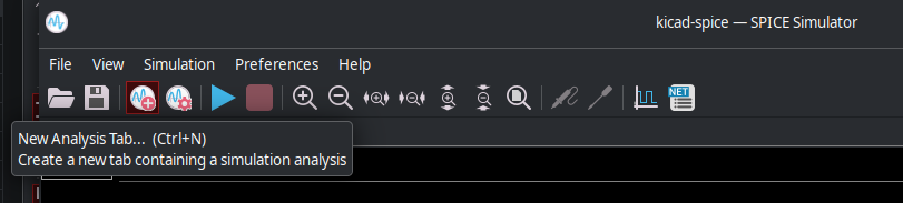
The “New Analysis Tab” option.
After that, you will need to tweak the simulation parameters depending on your needs. Since I wanted a transient analysis, I set it up with these parameters:
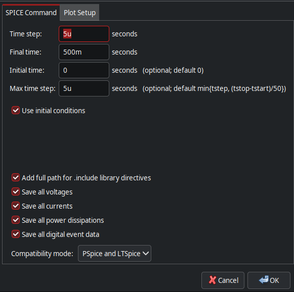
My settings for the transient analysis simulation I performed.
I left the plot settings at their defaults, but feel free to modify them as you wish. At this point, you can run your simulation with the big blue “Play” button, and use either the “Signals” tab on the right to pick which node you want to plot, or use the “Probe Schematic” button as seen here:
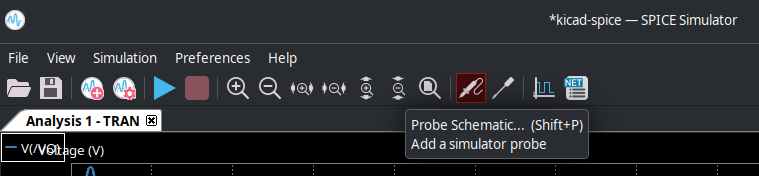
The “Probe Schematic” button with the “Add Tuned Value” button to the right.
Now, you should see your plot like this!
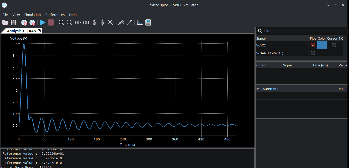
The plot of the voltage at the VO node in my RLC circuit.
Another useful feature is the “Add Tuned Value” feature, which lets you tune values and re-simulate automatically. In this case, I’ll tune the value of my resistor and see how it affects the circuit. The tunable values appear in the bottom right, and I tuned my resistor to be 1k instead of 10 ohms, and you can see the result:
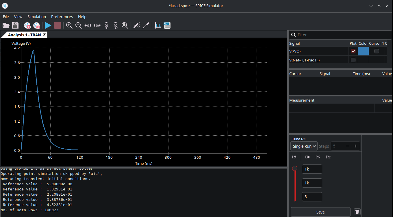
The smoothed out transient due to the higher tuned R value I picked.
There are many other features to experiment with, like cursors, measurements, and other simulation types, but feel free to try them on your own by using KiCad as your circuit simulator instead of LTspice. I think with enough practice, it can prove to be a very useful simulator in most cases, especially when already working on designs in KiCad.