Experimenting with a DC Motor Controller
One of my projects that I started even before working at M5 was converting an minibike to use electric power. At the surface level, it’s quite simple. You simply need a power source, a motor controller, and the motor. Initially, I chose to make my own motor controller using parts available at M5: a microcontroller, a MOSFET, and a gate driver. While this worked, it had its own issues and required external power as I didn’t implement a voltage regulator that was capable of stepping down the ~60v I needed. After letting the project sit for about a year when I realized I was in over my head, I decided to take another look at it with a fresh mind.
With this “second iteration”, I decided on using an off-the-shelf DC motor driver that was capable of handling the roughly 4kW I needed to get the full power out of the motor. However, when I actually bought a controller (admittedly the cheapest one I could find), I discovered a few issues. First and foremost, it needed a potentiometer signal to control the motor power, while I was using a Hall effect sensor. Secondly, it had a very strange design choice, which I will write about today: a low pass filter on the input! I have no idea why it was designed this way, as it would mean that when the potentiometer was swept from minimum to maximum quickly, the motor would actually spin up slowly as there was a time delay in the signal actually going to the controller.
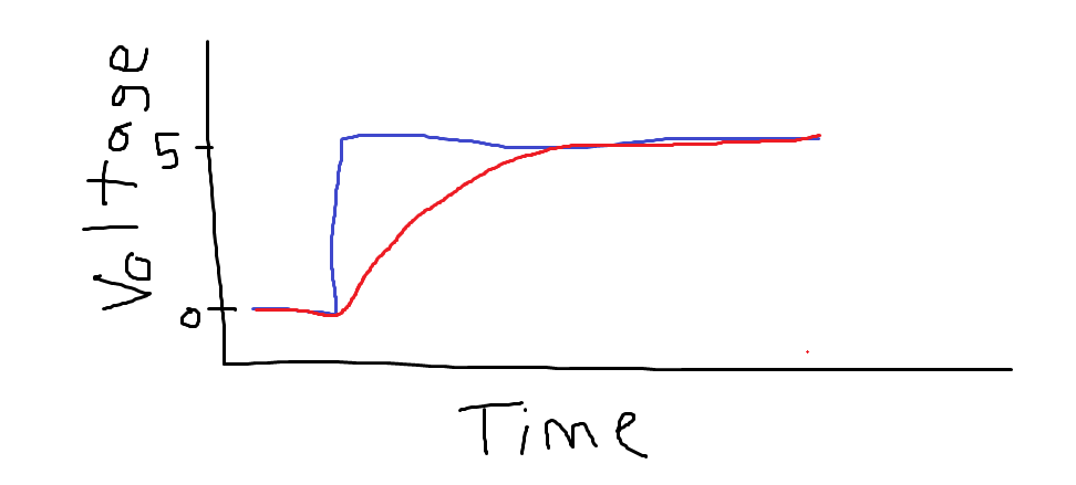
A very professional graph - blue represents the position of the potentiometer (how much power I want), and red represents the actual input the controller receives (how much power the controller thinks I want)
Through some experimentation, I discovered the RC low pass circuit on the PCB inside of the controller, and confirmed it using a multimeter. I then made sure that the capacitor I had was the correct one by adding a second capacitor in parallel to increase the equivalent capacitance. By doing this, I would affect the RC constant in such a way that would make the response of the potentiometer MUCH slower. When I did this, I did indeed find that the pulse width of the signal to the MOSFET gates* would rise and fall much slower when I moved the potentiometer.
*The controller operates by sending a PWM signal to the gates of the MOSFETs, basically affecting what percentage of time they allow current to flow through them. If you don’t know how PWM works, it’s a very interesting topic to learn about!

The signal at the gate of each MOSFET - the pulse width varies depending on what the potentiometer is set to, and the low pass filter affects how fast it changes, in the photo the duty cycle is roughly 50%
For the purposes I need this motor controller for, the long rise time would lead to an incredibly sluggish throttle response, and the long fall time would actually pose a danger risk: what if I need to suddenly stop, but the motor controller keeps sending power to the wheel? In the end, I chose to reduce the value of the capacitor for reasons I’ll explain in my next blog post where I discuss my solution to using a Hall sensor with the controller. This maintained the sharp throttle response while adding some needed smoothing to the input.
This is one of the more simple tasks you can use the test equipment at M5 for, but it would be quite difficult to know exactly what to do without access to a scope, a multimeter, and a power supply - all of which you can find in the Pi Room. Without the scope, I would be purely speculating as to what signal was actually being sent to the MOSFETs by the driver, and without the supply and meter I would be unable to even test the driver. To see what equipment we have that can help you, come visit M5 during our open hours and take a look!