Homemade PCB Workflow
Over the winter break, I spotted a good deal on a desktop CNC router. My plan was to buy it so that I could mill out my own PCBs from the comfort of my own room, and have boards to prototype circuits in minutes, rather than days from JLCPCB. After getting some copper boards and mill bits to use in the router, I’ve had some success, and want to share my workflow:
Just like as you would with a JLCPCB order, you can draw up a PCB in KiCad to send to the router. You export the .gbr and .drl files as normal, and then use the pcb2gcode command line program to convert those gerbers and drills to gcode, which will then instruct the router where to mill. This program lets you set the parameters for the router, so that you can slow down or speed up how much the bit will remove from the board in each pass, etc. to fine tune the results of the routing. You ignore the silkscreen and solder mask layers, because the mill isn’t capable of those operations.
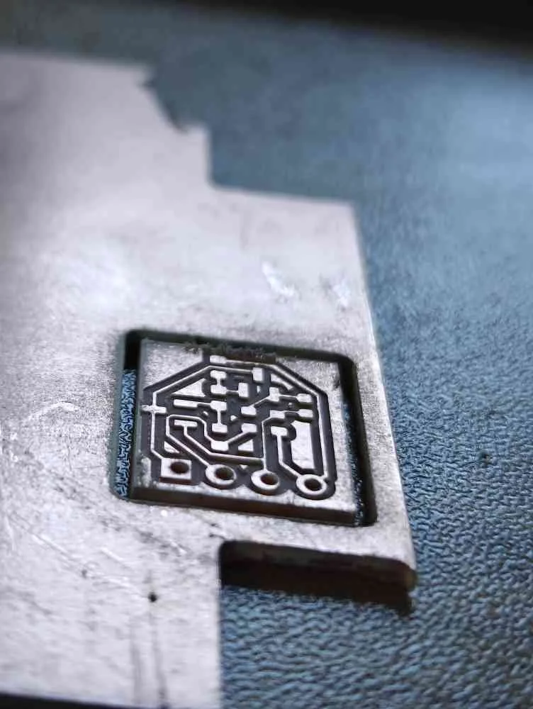
Once this is done, the rest of the milling process is rather straightforward. We clamp down a copper board onto the milling surface, zero our milling bit in the software to where we want the PCB to appear on the copper board, and run the .gcode generated by pcb2gcode. The gcode is split into a front copper layer, back copper layer, drill, and outline, so that the front copper is milled out, then the vias and THT holes are drilled out, then the board is flipped for the back copper traces, and then the outline layer cuts the board out of the copper sheet. After getting some practice with setting up and running the .gcode, I’ve been able to machine some beautiful PCBs at home. It can even do default KiCad netclass trace sizes of 0.2mm!
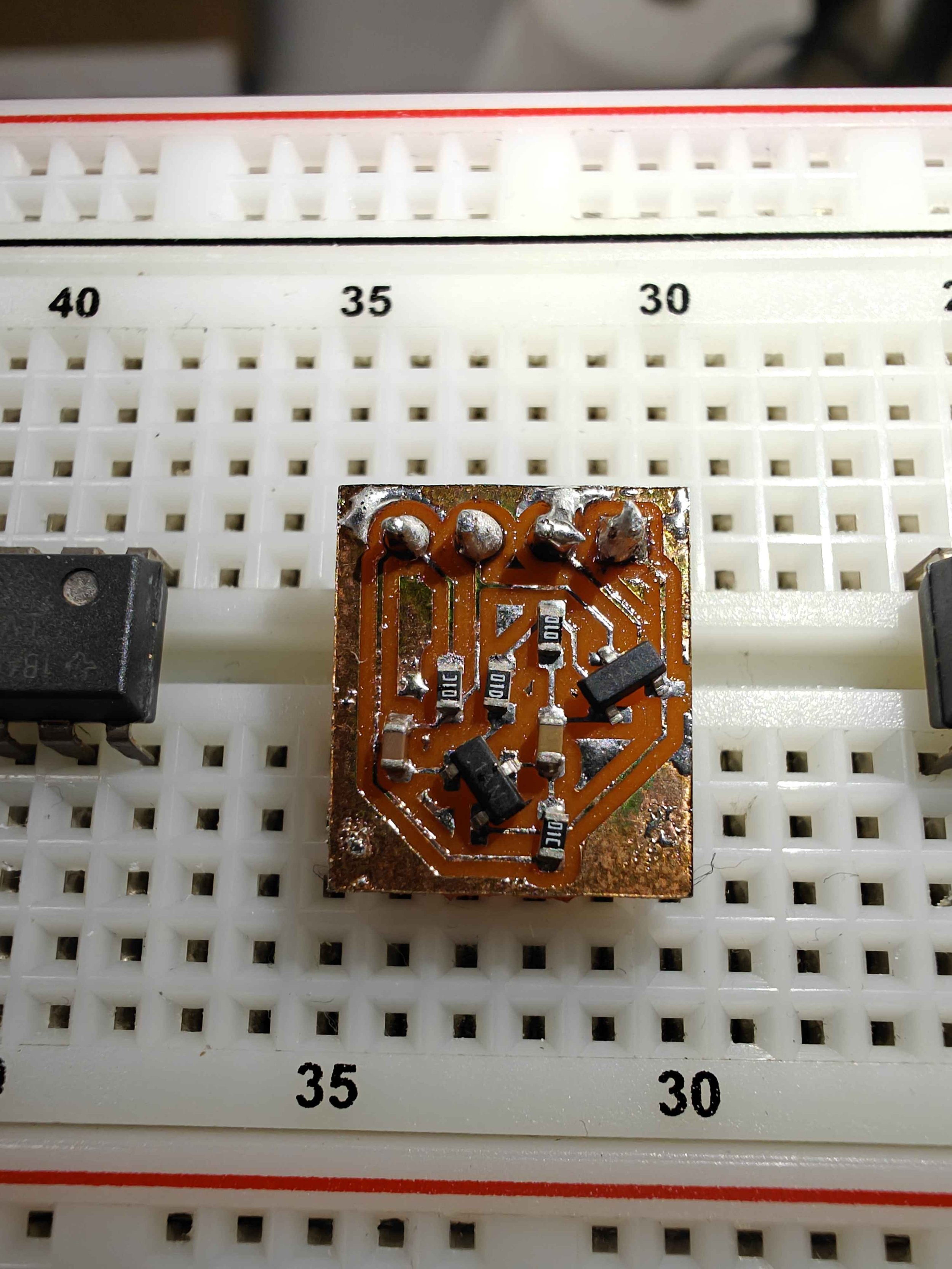
For my “Hello World” example, I made a voltage-controlled oscillator that I can use in a mini modular synth someday. The circuit uses an astable oscillator with a second input for controlling the frequency.
Here is a video of the router test milling a PCB front layer into a block of wood, followed by the mill result, soldered result, and operating circuit: