No analog pins? No problem!
“Hey, I’m here to wire up my speaker for my virtual desktop cat project.”
“Nice, that should be pretty easy, your project is almost done.”
Just as doctors and nurses never want to hear the word “quiet” when working, we engineers also don’t want to hear the word “should be easy” when working…
For those unfamiliar, Robert Mendoza is using a Pi Pico to execute the code for his virtual cat pet project here at M5. It’s perfect for his setup, since the SPI bus is very robust, which is needed for the display he is working with. However, there is only one problem with this particular board. There’s no onboard DAC!
Arduino Unos and a variety of other MCUs offer onboard DACs. A DAC, or digital analog converter can convert digitally encoded information into an analog output. If I wanted to create 2.4V on an Arduino Uno analog pin, I can simply write the code to do so, making use of the onboard DAC. One could then play audio through these pins by connecting to an amplifier, and then to a speaker, and coding the analog pins to play the samples of a sound. As for the Pi Pico, we’ll have to brush up on our ECE 311 knowledge…
Okay, we’re limited to only putting out 3.3V and 0V, and nothing between those values on a digital pin. If we’re very creative with when we switch the digital pins on and off, we may be able to use some sort of filtering to convert our output into something more analog looking.
As it turns out, we can create a carrier PWM signal that operates at a really high frequency, well above any frequency our analog signal would contain, and then modulate the duty cycle with the amplitude of our anticipated signal. Then, we simply pass the digital signal into an RC passive filter, and out comes our analog signal! This is how class D amplifiers work, by encoding the input signal into a PWM, and then the power switching is done by powerful transistors, and is then filtered.
The Pi Pico Arduino IDE board library already anticipates the user to do this, so the code ends up being as simple as
analogWrite(pin, sample);
delayMicroseconds(carrier_period);
// repeat for all samples…

Sine wave and its encoding in PWM
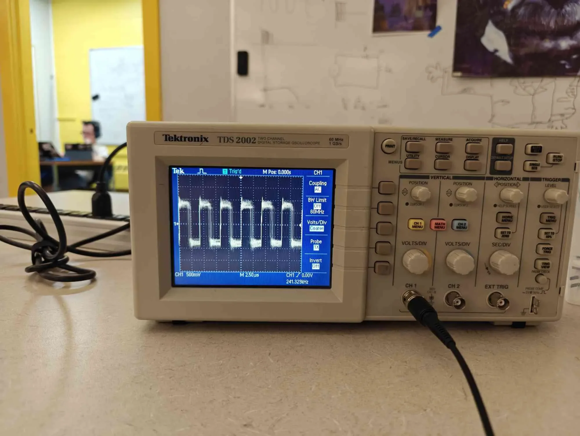
Our PWM at a small time scale
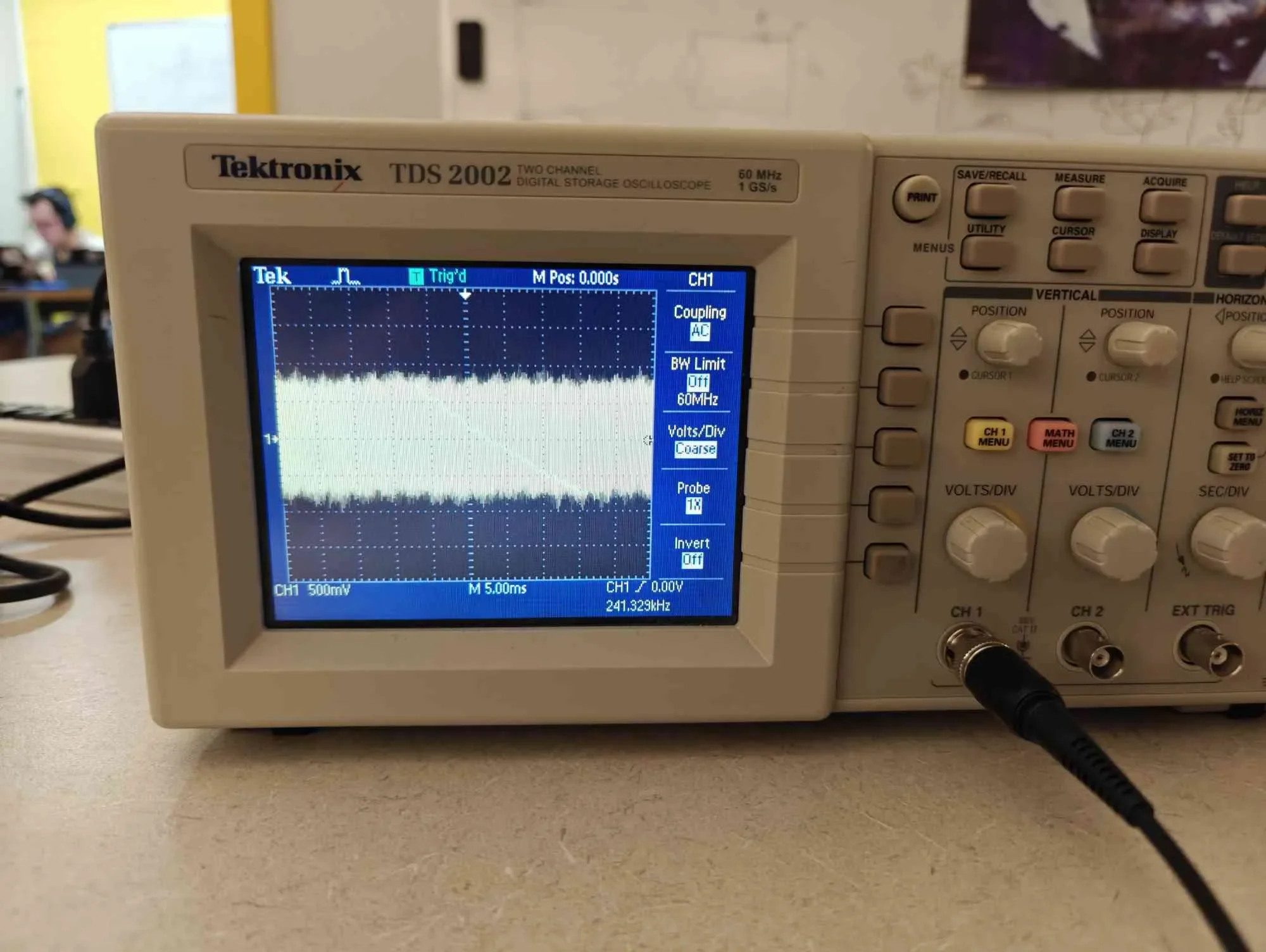
PWM at an audio-appropriate timescale
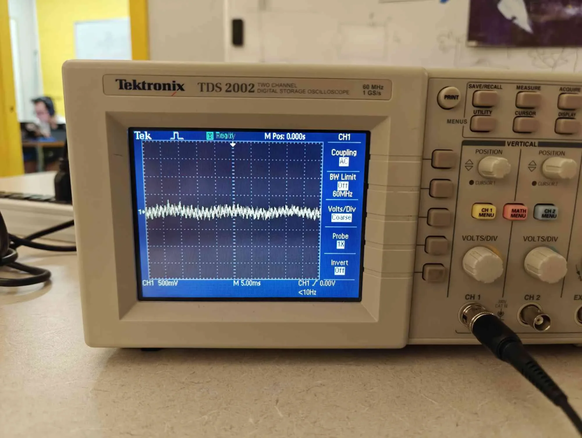
Filtered audio output going to the amplifier
Anyways, now that we have an analog signal, we use another capacitor series to the amplifier to isolate the DC that we may have accumulated, and then we can listen to the soft purrs of Roberto’s virtual cat!
Of course, we could always use a DAC off the parts wall, but isn’t doing it yourself cool?