Real-time processing power of STM32
Recently, I set out to get a little more familiar with the STM32 platform. My idea was to use an STM32 to work with a real-time signal, and I ended up deciding to take the FFT of an audio signal over USB, and display the resulting frequency bins on some LEDs.
I chose to use an STM32F401CBU6, due to its high performance with real-time signal processing and built in USB physical layer. We can also simulate a UAC-1.0 device using the STM32, which is nice as it is universal over most host computers.
I started with working out the USB power delivery network to the board. I needed to first filter the noise off the line, and step it down to the needed 3.3 V for the STM32 supply voltage. I used a ferrite bead to filter out high frequency noise and choke the inrush current when plugged in, and some capacitors to additionally filter the line. A low-dropout regulator, capable of pushing 500mA was used to step the voltage down.
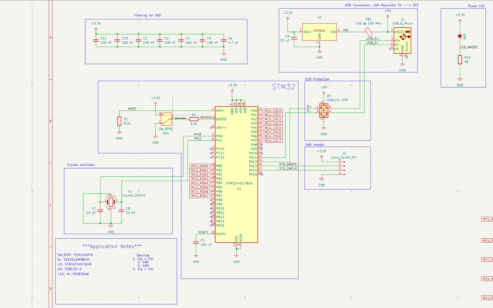
Schematic for the STM32, USB power & filtering, ESD protection, headers, and an oscillator.

Next, we needed some basic peripherals for the microcontroller. These included a 16 MHz crystal oscillator, pull-down on the reset pin, a switch for boot mode, connections to the USB differential data lines, and a header for the SWD and JTAG interface.
Following this, I then needed to decide how to drive the 8x8 LED matrix on the board. Using these dimensions, with each LED drawing ~5mA, we could stay under the power and current requirements for the LDO regulator and USB power supply, taking into account the additional draw from status LEDs, the eventual buffer IC, and the STM32 itself.
To drive the LEDs, the STM32 multiplexes high through each column, and drives the corresponding rows low to turn the LED on. At a fast enough rate (>50Hz or so), the human eye can’t perceive discrete changes.
In code, this would translate to grouping the 128-point FFT into 8 groups, averaging and normalizing to 8. In a nutshell, the STM32 fills a USB buffer with incoming data, then a flag is set, and it processes the data and puts it out onto the LEDs. I ended up using a double-buffer to save cycle time, where as one buffer is processed, the next begins to fill up with USB data such that data is not skipped over, and the interrupt that is set when data comes in behaves predictably.
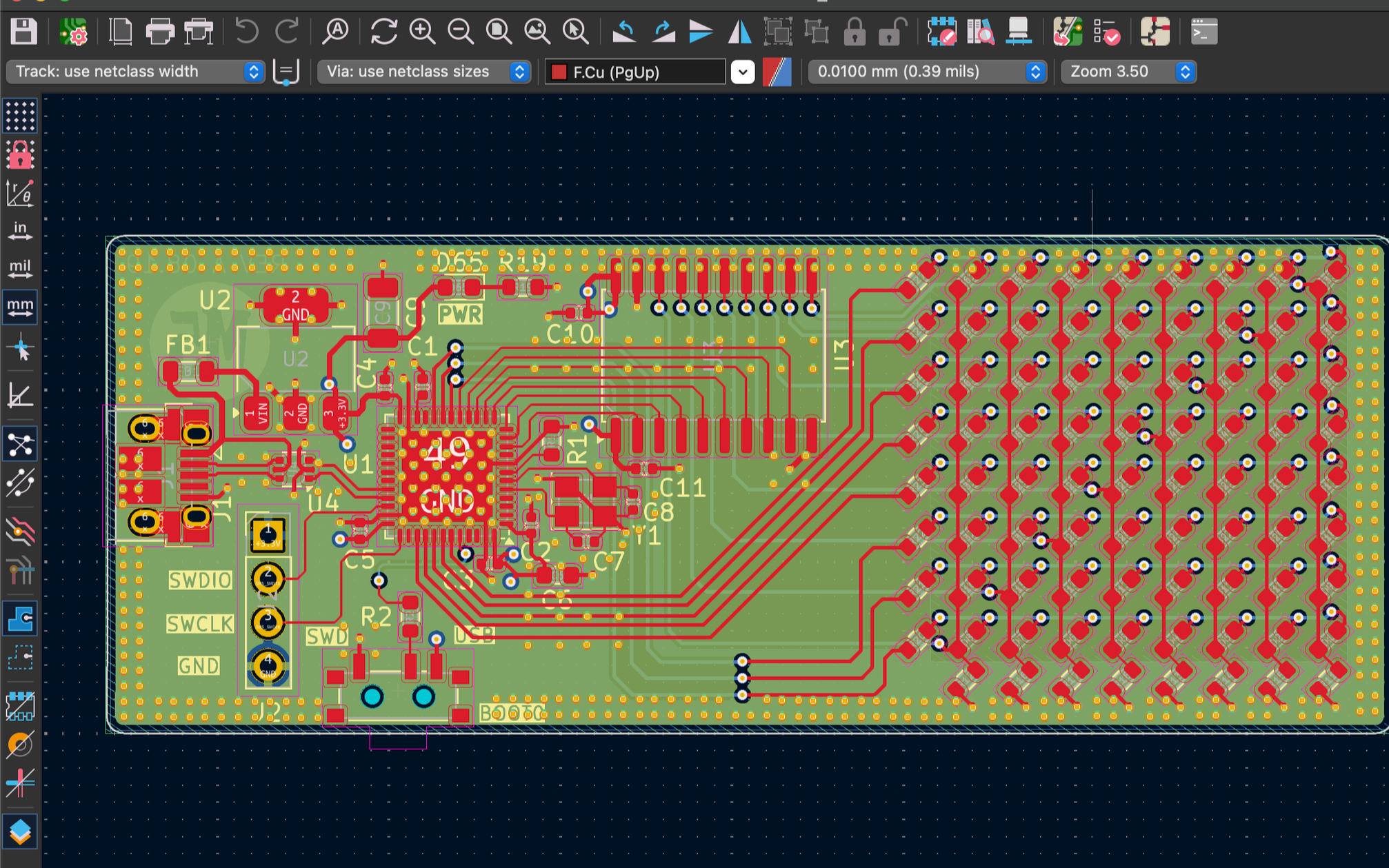
Final board design, in KiCad
Although this wasn’t exactly necessary for this board, high-frequency signals on a PCB need impedance-matched traces to preserve signal integrity, and minimize reflections. To do this, we need to control parameters such as trace length, width, spacing, ground capacitance, PCB dielectric properties, and more. There are calculators available online to help determine the differential/characteristic impedance of traces. I used one from Altium to match the USB data lines to a 90 ohm differential impedance.
Being a four layer board, lots of the vias above exist to stitch together the inner two ground planes. There’s a nice lecture on PCB grounding rules on YouTube (https://www.youtube.com/watch?v=ySuUZEjARPY) from Rick Hartley, which gives a lot of good insights on what really goes on with high frequency signals.
STM32CubeIDE and CubeMX offer very easy interfacing to the functions of the microcontroller. There are pre-built UIs to control the clock speed, PLL division, GPIO functions, as well as code generation for interrupts, USB setup, etc. This made the process of writing firmware a lot easier, as I only needed to set up functions to collect data on each interrupt when the buffer was full, run an FFT on it, and spit it out onto the LEDs.
This was my first time working with higher frequency and multi-layer boards, and I hope this gives a little more insight on the process behind expanding into higher function PCBs.