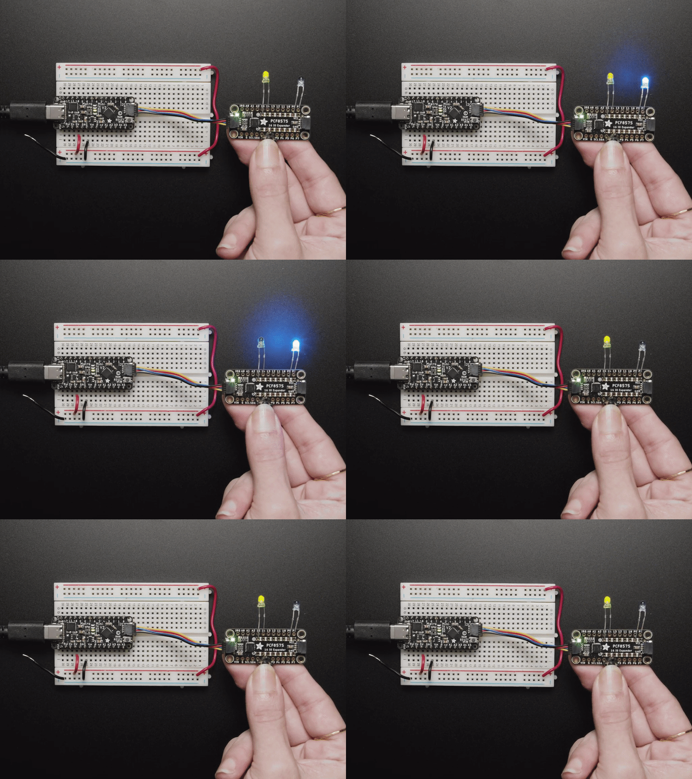
Using breakout boards is easy with qwiic connectors!
Whenever you’re thinking about what to do for your project, one seemingly difficult task can be interfacing different sensors with your Microcontroller board of choice (especially if you’re new to soldering). This is where products from Adafruit and Sparkfun can really help in the prototyping process. In this small article, I want to very briefly introduce you to the Qwiic connector :
Shown here is the Qwiic (4-pin Japanese Solderless Terminal connectors) cable interfacing a Metro V2 MCU board with a PCF8575 I2C 16-pin General Purpose Input Output (GPIO) Board to control two LEDs using a push button
What the Qwiic connector family provides, is a simplistic way to connect together different breakouts via I2C without the need to solder connectors. You are able to daisy-chain devices together since every single I2C device has its own address (within a 7-bit wide address space). With daisy-chaining you can connect sensors, displays, switches, and even Qwiic connector hubs!
Now that you have a wired up project, you might be asking what to do next, well the answer is always on the product page for your I2C device. Often times, a sensor breakout board has documentation on GitHub containing the library your sensor utilizes to make data collection possible for your chosen microcontroller.
Next time you’re looking for ways to get something working quickly, check out the sensors part of the M5 parts wall in the Pi Room!

