How did old tachometers work?
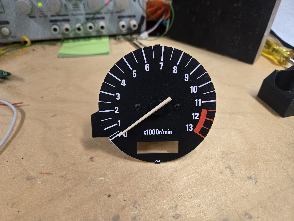
While going through parts for my senior project, I found the gauges from the motorcycle we salvaged the engine from. I felt it could be interesting to either use this tachometer as-is, or to repurpose it for something else. In any case, I wanted to have a way to digitally control it.
The vehicles that these came on typically didn’t have many (if any) digital electronics on-board. For example, the ignition was controlled by an igniter that fired when the crankshaft was at a specific angular position. On tachometers of the era, a voltage pulse was sent directly to the tachometer every time one of the ignition coils fired. Then, an IC inside of the tachometer would convert the frequency of these pulses into an output voltage, and this voltage was used to move the needle of the tachometer.
This tachometer that I’ve been playing with has three input pins: ground, power in, and signal in. By applying 12v across the power pins and a 0-12V square wave to the input pin, the needle on the gauge moves! In order to control the output of the gauge, I simply change the frequency of the wave. The control PCB also has a calibration potentiometer which can be used to fine-tune the output of the gauge.
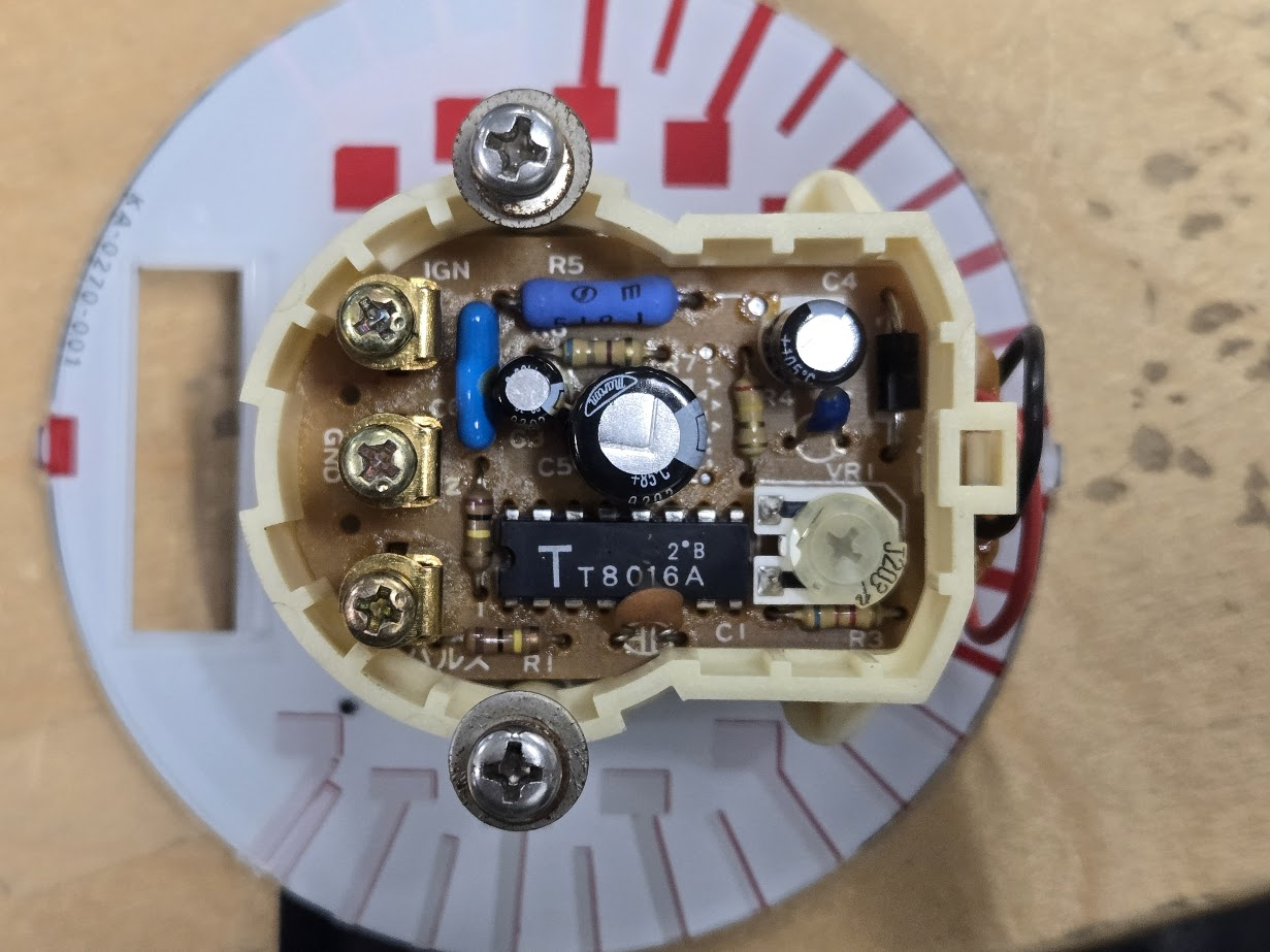
The IC shown converts a an input frequency to an output voltage capable of sourcing current, which is sent to the actuator that moves the needle
The needle actuator is controlled directly by the voltage put out by the control circuitry. The rotating piece has a coil of wire that, when a voltage is applied, will create a magnetic field. Because this coil is wrapped around a circular magnet, the opposing magnetic fields will create a force that moves the needle.
The magnetic field generated by the coil is directly proportional to the current passing through it, and because the coil is a passive component, the current is linearly proportional to the voltage. This makes it very easy to control the magnetic field with a voltage source, which means that voltage can linearly control the torque applied to the needle. This torque will in turn always reach equilibrium with the force of a spring inside of the gauge at a degree of rotation. This way, voltage applied to the coils can directly control the position of the needle with a fair amount of precision.
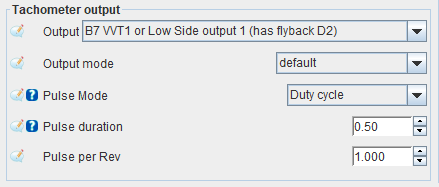
Modern standalone ECUs, including the one I have, have features built in to control tachometers like this. This makes it easy to run a few wires to the gauges that might already be in a car, and magically have a working tachometer.
With the advent of cheap and powerful control circuitry, stepper motors have generally taken over as the preferred way to move a gauge. They’re much more precise, can be digitally controlled, and are simpler to design around. However, it’s always interesting to look back at the solutions that existed before the digital era and see what was possible with simple analog electronics.