How does stuff get stored?
Have you ever wondered where your programs are stored on a micro controller? All micro controllers seem to be able to run their programs even after you cut their power and turn them back on, indicating that they have the ability to store your program in a non volatile place on the board. But how? This blog will cover some of the standard storage formats used, and how we got to flash storage.
The start: PROM
One of the initial ways to store data in a non volatile format (that is to say, storage that doesn’t require constant electricity) was to use PROM’s (Programmable Read Only Memory). PROM’s could only be written once, which meant that they could never be erased. This actually worked by using fuses! A PROM would come from the factory with continuous fuses, which would be read as a 1. With a special device, which would use a high current pulse to blow the selected fuses, you could programatically store 0’s in the selected slots.

An example of a PROM chip, with a diode and fuse array. The diodes prevent current from hitting any unspecified fuses.
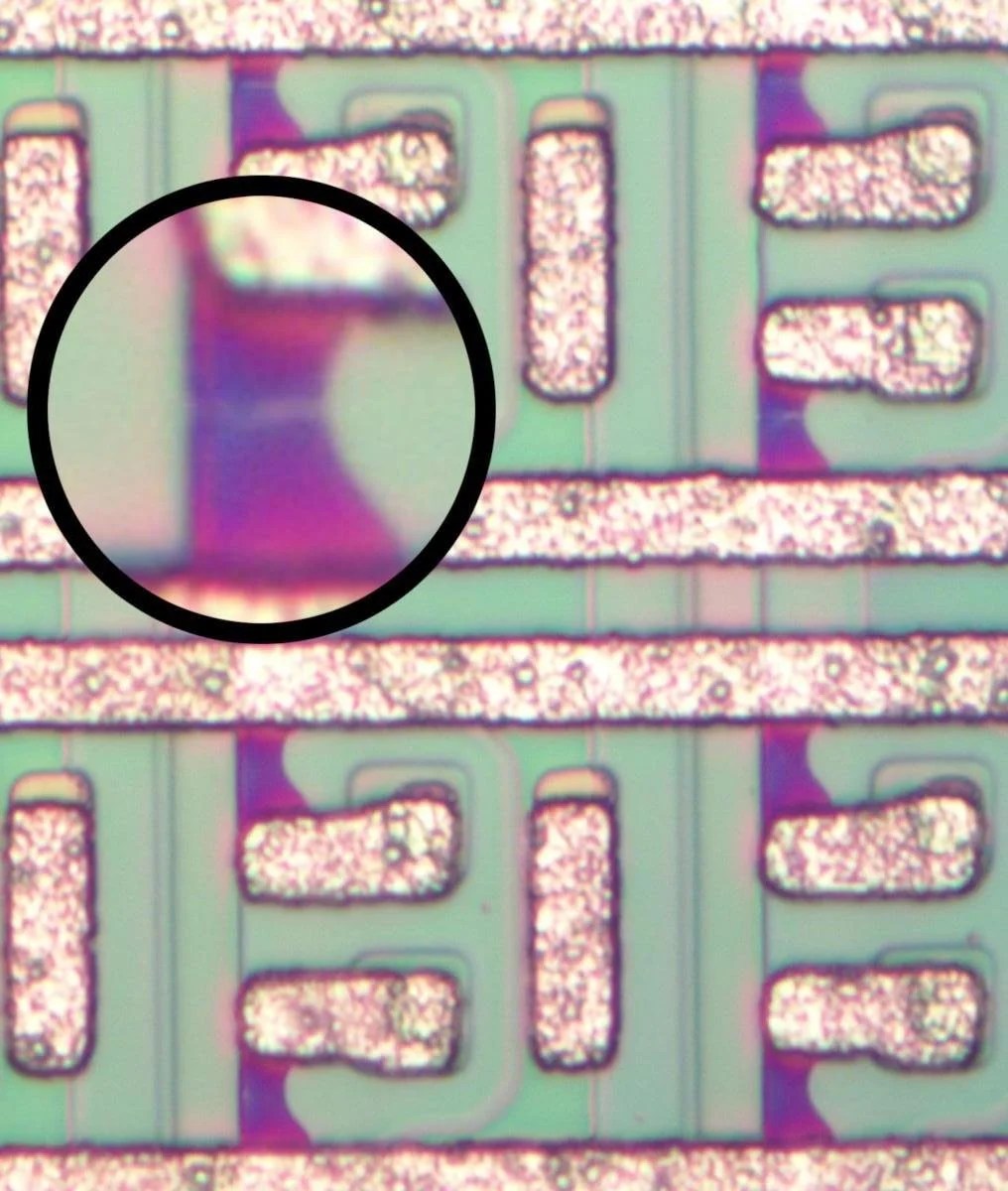
An example of the fuses. The fuses are the purple region, and the zoomed in one showcases the break preventing the continuity, and reading a zero.
if you find this subject interesting, I HIGHLY recommend giving https://www.righto.com/2019/07/looking-inside-1970s-prom-chip-that.html
a read. This article goes into detail about the full design of these, including how to access memory addresses.
EPROM: PROM but erasable!
After designing the PROM, the EPROM (Erasable Programmable Read Only Memory) was designed. This was to include a way to reset the PROM chip, so it could be programmed with something else. This was done by using floating gate MOSFETs. Floating gate MOSFET’s are MOSFET’s that have been modified to have multiple gates. One gate is the usual control gate, and the other is a floating gate. The floating gate is a piece of metal that’s between the gate oxide layer and the substrate oxide layer. Since the floating gate is sandwiched between two oxide layers, any charges that get trapped in the floating gate wont leak into the channel gate or the substrate layer.

a floating gate PMOS
By using a high voltage, we can accelerate electrons to high enough energy states that they pass through the oxide layers into the floating gate. This will store electrons in the floating gate, and since the floating gate is surrounded by insulating layers, they can stay there for up to 10 years! These electrons will generate their own electric field that points in the opposite direction of the gate voltage. Because of this, more voltage is required at the gate to cross the threshold voltage of the transistor.
Since a 1 that’s stored in this model needs higher voltage than a 0, we can simply see if passing a regular threshold voltage conducts or not to test whether we’ve stored a 1 or 0!
But how do we erase what we’ve stored on this chip? Our main goal in erasing is to free the electrons that are stored in the floating gate. To do this, we expose the dies of the chip to a strong UV light, which gives the electrons enough energy to ionize, and dissipate through the oxide layers. Have you ever wondered why the KIM1 board has chips with tape on them? that’s to prevent UV light from resetting the data stored on the EPROM’s.

The two EPROM chips on the KIM-1
Electronically Erasable Programmable Read Only Memory: the final boss of the ROM world.
Instead of having to use a UV light, and high voltages, what if you could just control two voltage levels, and instantly store data? That’s how EEPROM’s work! By using really thin oxide layers (like 10nm thin), and by sending a somewhat high voltage, you can cause electrons to tunnel through the tiny gap. This will cause them to get stuck in the floating gate again, and allow you to read the memory state like usual. How this differs from the EPROM, is that to write a 0 back to the MOSFET, you can simply supply a negative voltage, so that the charge dissipates from the floating gate. The difference between the EPROM and EEPROM is that the oxide layers are very thin, which allows an opposing electric field to interact with the charges inside the floating gate. However, the problem with the thin oxide layers is that over time the electric fields might cause electrons to be trapped in the floating gate, which could cause the threshold voltage to loose its stark difference between the 0 state and 1 state, or the electrons might slowly leak into the substrate, causing charge loss. This means that there’s both a write limit, and time limit to EEPROM’s. Write limits are usually around 100k to 1 million, while the storage time for a EEPROM is 10 years.
FLASH Storage
If I’m being honest, the topology of FLASH storage scares me, and I wont be going into it today. Here are some cool pictures of it though!
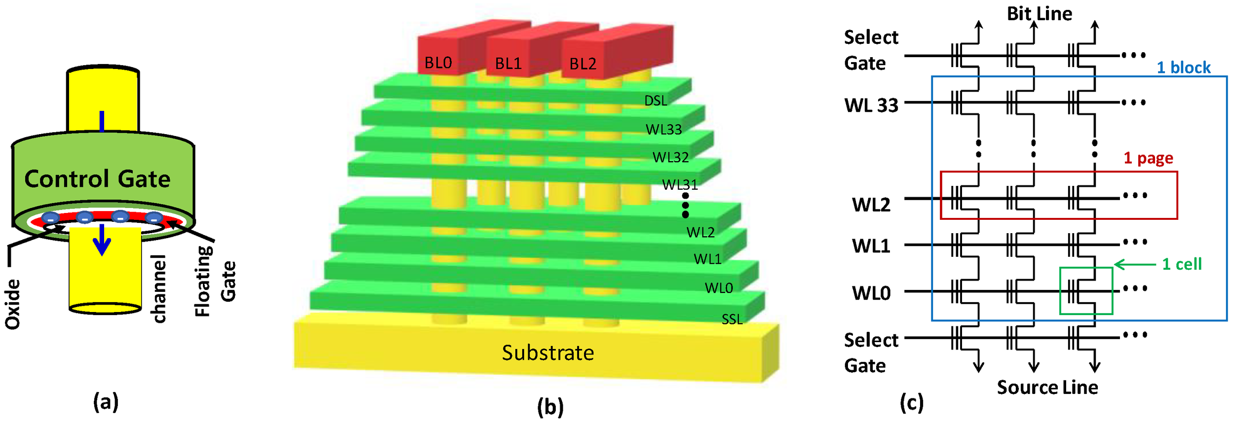
pyramid
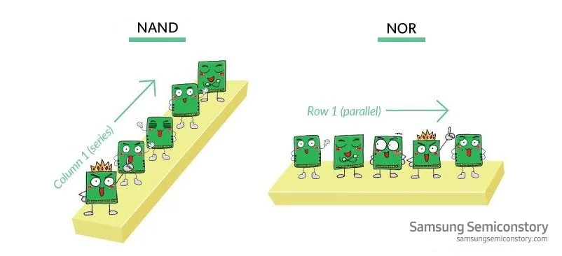
I don’t know why they are so happy
From a higher level perspective though, there are two types of Flash storage. One is NAND Storage, and one is NOR. NOR is often used in micro controllers, because it can directly access memory slots, which is helpful when executing programs. NAND allows for higher density storage because it requires serial access. This is better for storing large data, as large data often needs to be read serially anyways. NAND is in USB drives, SSD’s, and other storage devices. The one downside to flash storage is that it has a more limited write cycles. Typically, this is around 100k. flash memory is also sectored into blocks, which means that generally a whole block has to be erased. This means additonal circuitry, such as wear level protection (spreading out writes across the flash storage, so that minimal overwriting is done), and smart erasing is required This is why it’s common advice to keep 10-15% of your ssd free! this allows for less garbage collection cycles, which means less overwriting happens on the SSD.