How many electrical systems go into making an engine run?
Depending on who you are, firing up an engine might seem like either a very trivial or a very difficult task. At its core, there are three main things that go into making combustion happen: fuel, air, and spark. For my Senior Design Project, I’m in charge of making our engine run, and this will serve as an overview of what I have to do.
For starters, the engine needs to have fuel to burn. Many different engines have different ways of deciding exactly how much fuel to give the engine, but the principle is largely the same. Some common methods include speed-density, mass-airflow sensors, or alpha-N. All of these use various sensors to estimate how much airflow is entering the engine, and then the ECU (engine control unit) will inject however much fuel it calculates is necessary to maintain the requested air-fuel ratio. As I’m using an off-the-shelf ECU, my main goal is not to write the algorithms to calculate fueling, but rather to actually implement it. Fuel injectors typically work with low-side switching, meaning that each injector is always connected to 12 volts whenever the ignition switch is on, but the ground is switched on and off. Having the switching occur on the low side makes the control electronics much easier and affordable. The only real disadvantage of this method of switching is that the load is not grounded at all times, meaning a short-circuit to ground could cause more damage. However, this is a rare enough situation that low-side switching is still generally the default when it comes to driving fuel injectors and other inductive loads like solenoids.
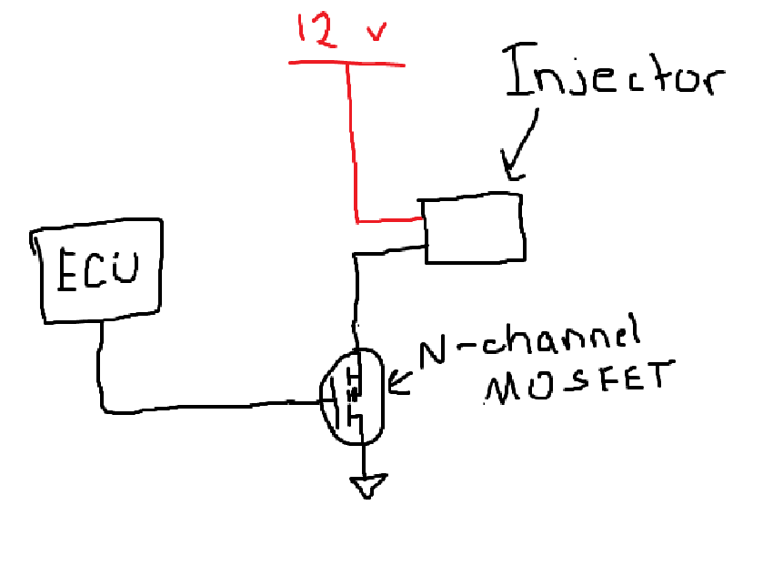
Very good circuit diagram of each injector
Now that fuel (and air, sort of) are taken care of, the mixture must be ignited inside of the cylinder at the correct time so that the expanding gas can push the piston down, and make power. This is the job of the spark plug, which receives a very high voltage from the ignition coil. The ignition coil is also an inductive load, so naturally it uses a very similar control system to the injectors. The main difference between the injectors and the coils is that the coils take much more current to drive, and have a higher inductance. This means that the kickback is much higher, and the MOSFET must be configured to handle a much higher voltage spike after shutting off. Typically, IGBTs are used as they can withstand a very high Vds without failing.
Now that the ECU is able to drive the injectors and ignition coil, how does it know when to fire? That is the job of the crankshaft position sensor, typically either a hall-effect or variable reluctance sensor. Both of these are contactless and thus don’t suffer mechanical wear, instead operating by using magnets or a ferrous toothed wheel to generate a moving magnetic field around a sensor. The sensor then picks up the pattern of the signal, and depending on the frequency, it knows the speed. However, this only gets us the engine’s RPM, but we need to know absolute position as well. This is usually done with a missing tooth/magnet in whatever is rotating, so that the ECU can detect when a signal is skipped. Once the engine knows this, it can then pick a precise rotational precision to ignite the mixture. For example, the ECU can charge up the ignition coil 2ms before it reaches 10 degrees before the piston is at the top of the cylinder, then discharge the coil and create a spark exactly at the correct time.
When all of this is combined, you have an engine that runs! After a decent amount of work, we managed to get our engine to fire spark, and soon it will be able to inject fuel as well. Here is our engine firing up: