Heart Shaped PCBs
If you are a good ECE student who reads all your emails, you probably heard about Saturday Makerday!
If you missed it, here is a recap of my Intro to KiCAD workshop where I made heart shaped PCBs!
Here is the final product to further convince you to keep reading:

First we start with creating the schematic:
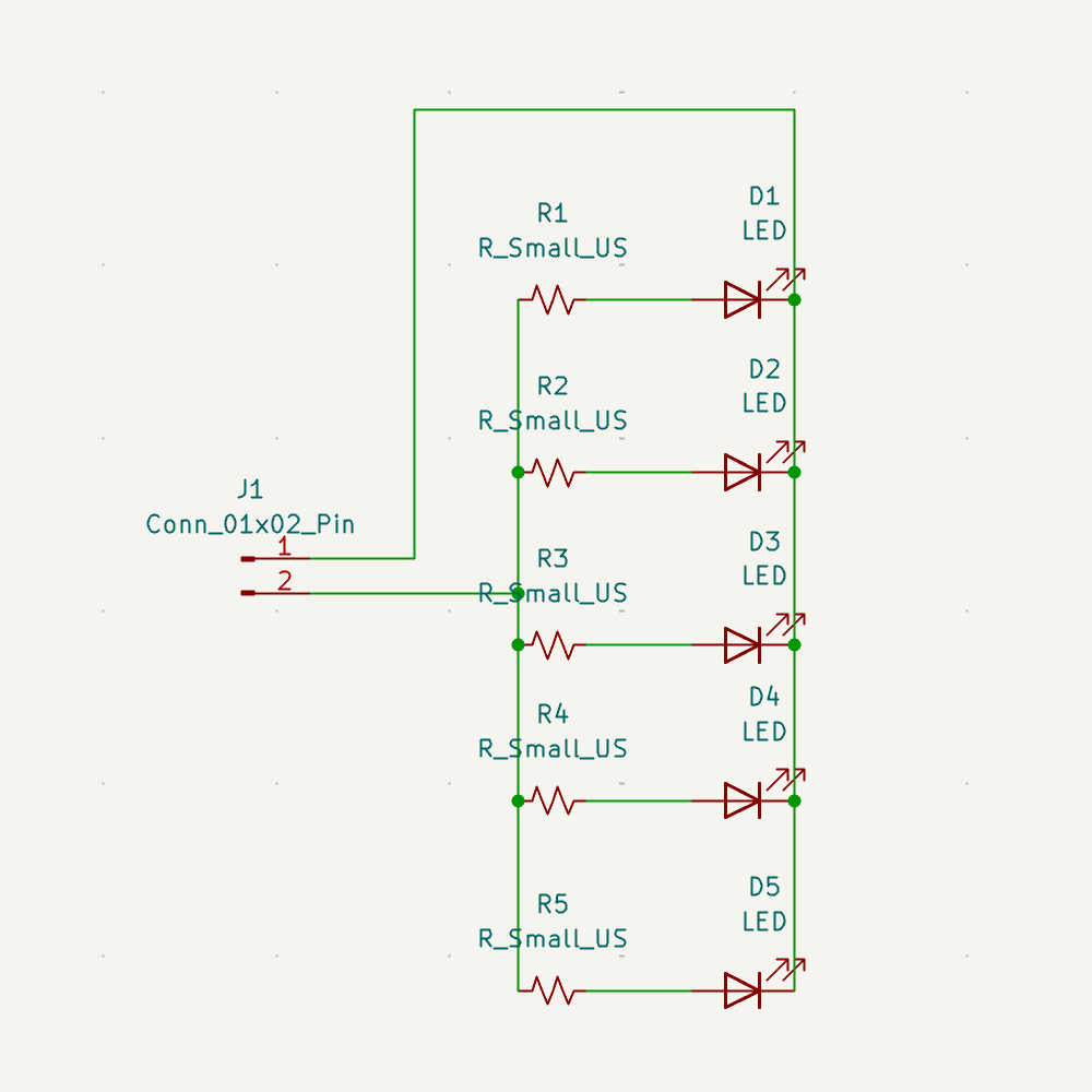
It’s a pretty simple circuit just consisting of LEDS, Resistors, and Header Pins.
Something super important to do in KiCAD is to make sure that you have the right footprints. This allows you to have a picture when you are designing in the PCB Editor to ensure accurate wiring!
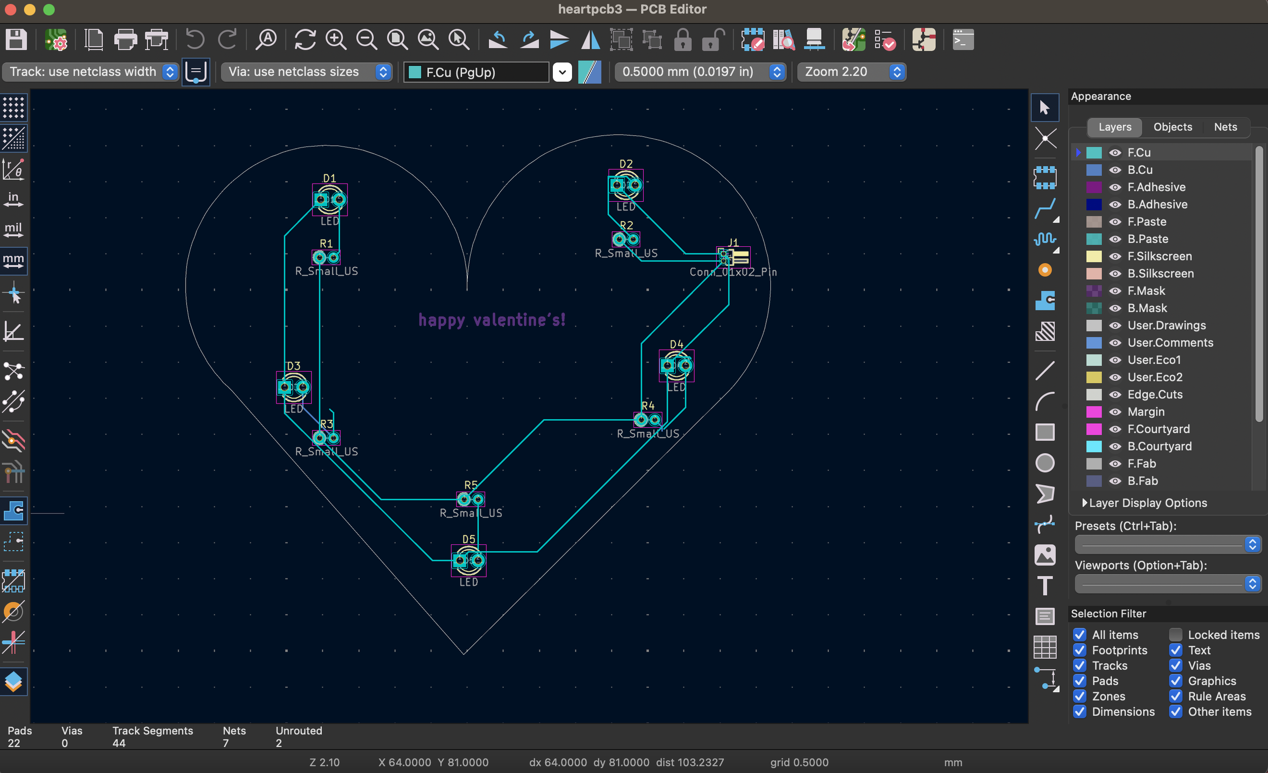
Once you finish your schematic, you can head over to the PCB Editor!
You can hit the Update from Schematic to get all your parts into the editor.
You can create the heart shape by 1. clicking on edge cuts 2. clicking on the arc symbol and creating 2 arcs 3. clicking on line to create the base.
Once you arrange all your parts onto the heart, you can start wiring! If you hit the circle, your path should light up. If you hit F, KiCAD can wire it for you using the most optimal path!
Make sure to check all your wiring using the Design Rules Checker feature!
Now go to 3D Viewer and your PCB should look like the cover image!
Congrats! You just finished making your heart-shaped PCB!