Reading an Analog Telephone Line
In order to get cool data to power blinking lights and graphics on our next telethon, Toby and I are trying to get a circuit together to allow a basic ADC to read the audio on a telephone line. However, this has one basic challenge that we must overcome.
This challenge comes from the very nature of telephone lines: they are held at forty volts DC when the phone is on hook, and in order to ring the PBX sends a 75VAC signal down the line. There aren’t many cheap, easy to obtain ADCs that can handle this kind of abuse, so we must find a way to isolate the ADCs.
I came up with three possible solutions to this problem. My first, somewhat naive solution is to just put a high enough impedance between the ADC and the line that overvoltage protection won’t cause any problems. You can do this with a massive resistor and can shunt the overvoltage to some reference rails provided by a zener diode. You can do this with the circuit below, however a quick back of the envelope calculation treating this circuit and the required pcb trace as a low pass filter gives a cutoff frequency around about 6KHz. This is exactly the audio bandwidth of a telephone line, so there isn’t much room for error.
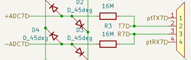
Naive solution to the problem.
You could also solve this problem with four mosfets and a voltage reference. this way the mosfets only turn on when the difference between the two sides of the phone line is less than the reference voltage. This solution likely works, however it requires a large number of components, and if one of the mosfets fails due to a voltage spike the entire system fails and you lose an ADC.
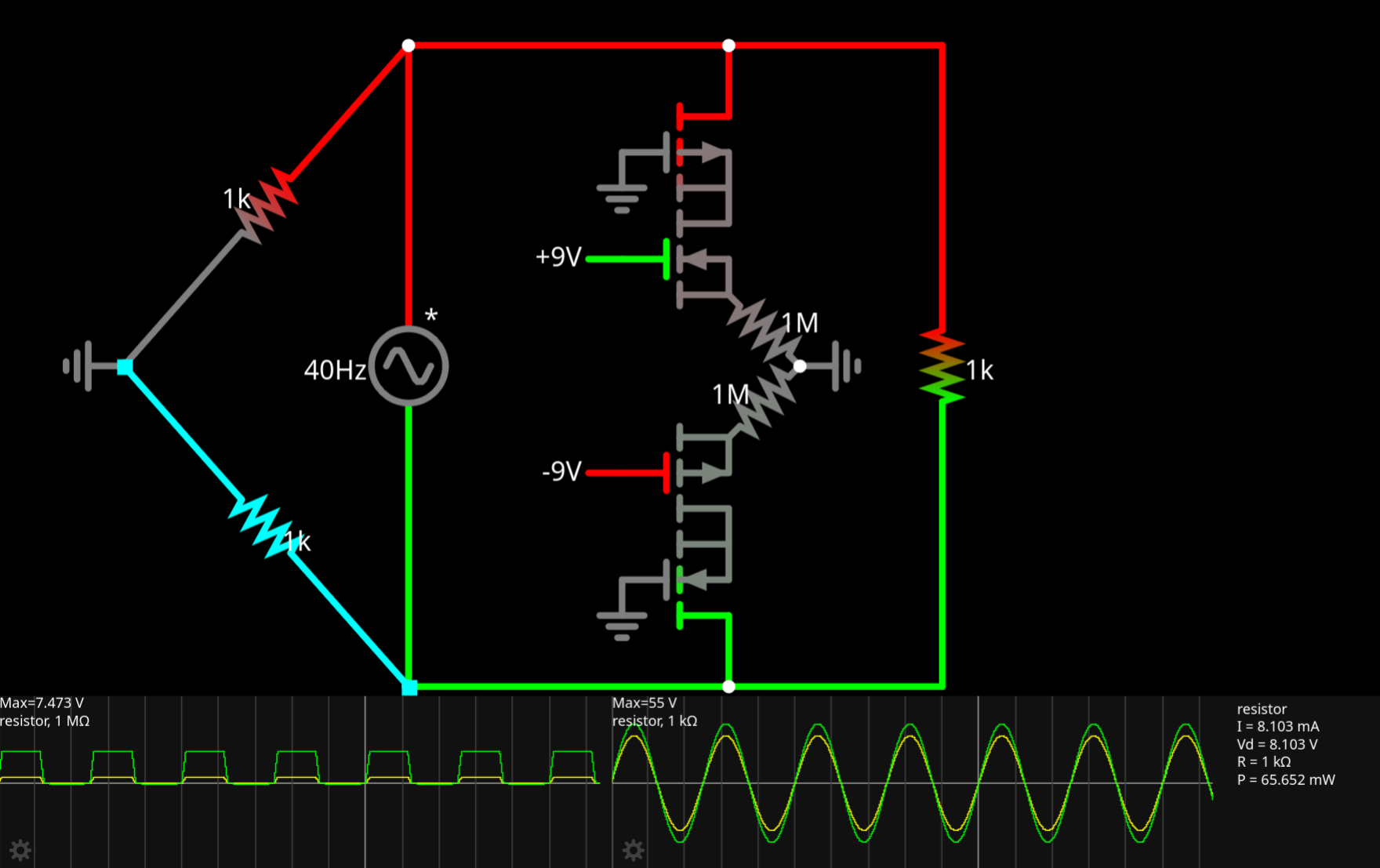
Mosfet based solution
Fortunately, there is already a solution to this problem, and it’s been around for decades: the humble Optocoupler. With this device I can turn the current on the phone line into a voltage, while keeping the phone line and the ADCs electrically isolated.
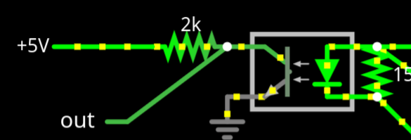
Example optocoupler circuit.
This third solution is tried and tested, with the sole possible issue being the voltage drop due to the diode. If you wish to know more about Optocouplers, check out Robert’s blog post about light dependent resistors, which behave similarly.
Fortunately, I have a service manual for the pbx, meaning I can identify and recreate the powersupply circuit in a circuit simulator, to verify that it works.
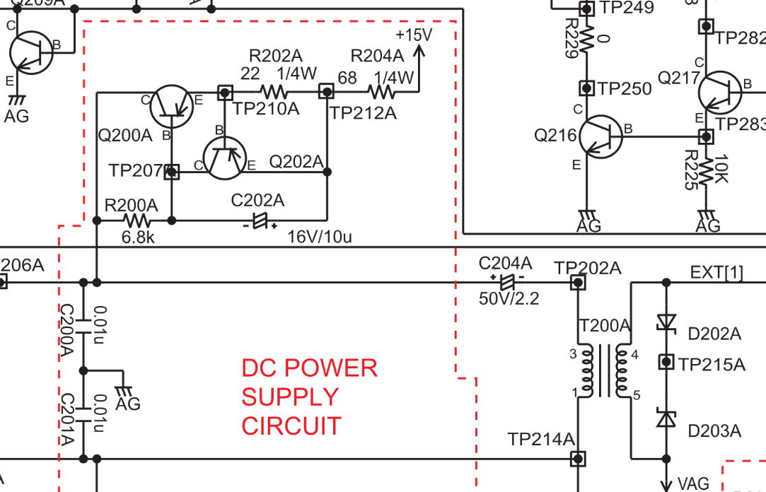
Current limiting DC power supply for the phone line + transformer.
Recreating this circuit in a basic simulator shows that it is a relatively simple current limiting circuit. As current goes up it behaves as a larger resistor. This has the effect of nullifying the voltage drop across the optocoupler, providing a stable voltage down the phone line.
The circuit I used to test this is messy, so I didn’t show it, but if you want to check my work, you should recreate it yourself! Here’s a link to the simulator I used. Happy prototyping!