Let There Be Light… Dependent Resistors!
It’s not uncommon to want a varied resistance in a circuit, for example to control feedback in an amplifier or the cutoff frequency in a filter. While a simple potentiometer would work well for this, they still need to be mechanically controlled. If you want to have this resistance controlled electronically, there’s a much better solution: the photoresistor!
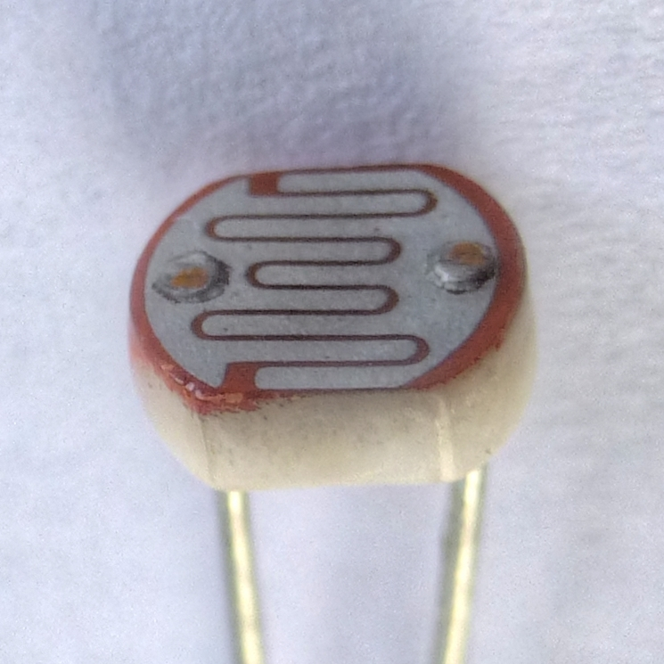
Image © Nevit Dilmen, CC BY-SA 3.0 https://creativecommons.org/licenses/by-sa/3.0, via Wikimedia Commons
These little passive components have a resistance that varies based on how much light is hitting the surface at any given time. This makes them great for light sensing, but also presents the ability to put a light next to the photoresistor inside of a dark housing, making it so that the brightness of the light directly controls the resistance across the photoresistor. This is known as a resistive opto-isolator (commonly known as a Vactrol), which is a specific type of optocoupler.
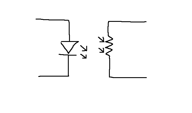
High-quality rendering of what a resistive opto-isolator actually is
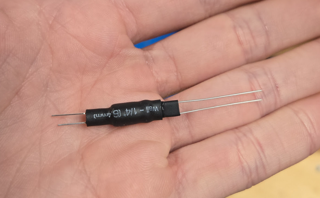
An optocoupler I made at M5 with heat-shrink, a CdS photoresistor, and a green LED
Originally, I was tasked with creating this opto-isolator as a method of obtaining digital resistance control for a demo to be shown in the Junior Design Project lecture, a class for which I am a UIA. It was made with several very low-cost parts from M5, which you yourself can make!
In order to test this opto-isolator, I made a small passive RC filter which was then buffered through an op-amp so I could plug it into a set of speakers. I then had a microcontroller apply a PWM output to the LED, which directly controlled the resistance across the opto-isolator. The result was a digitally controllable low-pass filter!
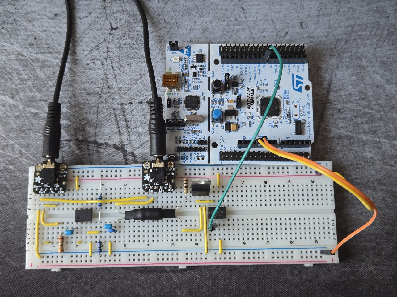
This circuit uses a simple transistor and gate driver to control the LED directly from the voltage supply rails, so it draws nearly no current from the GPIO of the microcontroller. The LED in turn controls the photoresistor, which is used as the R in the RC filter. The output is then isolated, biased to be within the range of the op-amp, and then isolated with a capacitor so it oscillates about 0V rather than 2.5V. It’s not a very good filter, but the opto-isolator is definitely not the part holding it back