Man, I wish my Arduino could output 32V…
If you’ve somehow stumbled across my previous blog posts, you may be familiar with my homemade modular synthesizer. After getting a PCB mill over the winter, I’ve been making small boards to plug into my synthesizer, with the first successful prototype being a voltage-controlled oscillator.
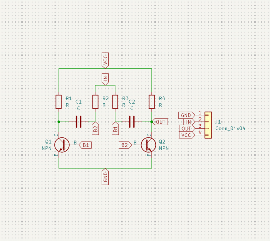
This is the schematic for the oscillator that I turned into a PCB. It works great, apart from the fact that the output frequency barely changes with the input signal level. This is because most voltage-controlled oscillator circuits use transistors in a more elegant way, making the current through the RC network more exponential rather than linear. This allows a smaller input voltage change to produce a larger frequency sweep.
Instead of solving this issue directly in the oscillator, I decided to make another board to support a larger voltage range. In my testing, I can get the oscillator to output frequencies spanning the entire 88-key piano range if the input control is between 0 and 32 volts. But how would I make an Arduino produce that signal level if its pins can only output up to 3.3V?
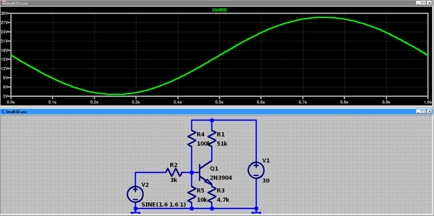
Ah, the humble inverting BJT amplifier. With the right choice of resistor values, we can map a 0–3.3V input sweep linearly to a 3.3–30V output signal, giving the oscillator a much wider frequency range.
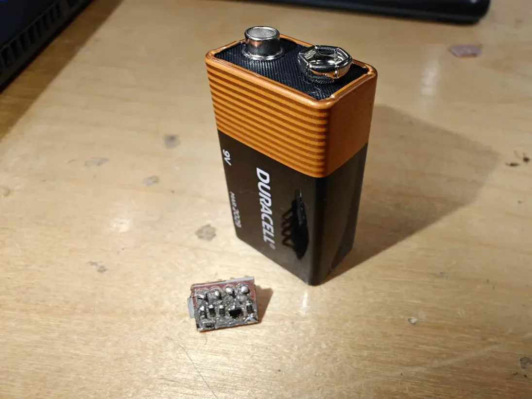
Here is the completed circuit, with a 9V battery for size reference. Now we simply test the output voltage for input voltages between 0 and 3.3V, as expected from an Arduino:
The output range isn’t perfect, but for my purposes, it works great!
Karl Kreuze
Electrical & Computer Engineering, 2026
28 February 2026