My Circuits and Code project: A 6502 based MIDI Controller
Hey there, I hope you had a fun time visiting Circuits and Code this year! If you couldn’t make it, you can always watch recaps of all the unique projects designed by ECE students on the M5 YouTube page.
Through my time taking the ECE 287 course, I had spent the entire semester understanding the 6502, a famous 8-bit microprocessor that was developed in 1975. To program this CPU, we used a KIM-1, a development board which supplies the essential components to the CPU, such as the RAM/ROM, a clock signal, and a 7 segment display with a keypad to individually program memory addresses with data and assembly instructions. This course allowed me to gain a deeper understanding as to how computers function, and how programmed instructions get parsed by the CPU.
For my final project, I designed a program to store and send MIDI (Musical Instrument Digital Interface) messages, which could me sent to any MIDI compatible synthesizer to make music.
MIDI Protocol Explanation
The MIDI protocol is based on UART (a protocol used to transmit data between devices), and uses a single data line that idles at 5v, and when active, sends MIDI packets that control the synthesizer. MIDI packets are defined as 8 data bits, with a start bit (0V) before and a stop bit after (5V). MIDI messages also need to be sent at a defined frequency, which is 31,250 bits per second. This frequency is known as the MIDI Baud Rate.
The MIDI protocol requires three packets to be sent:
Status Byte: Prefaces the rest of the data with what data is being sent, such as which device should respond (the MIDI channel), if a note should be turned off, and additional information, such as changing the music kit of the synthesizer.
Note Byte: defines the note to be played. eg: a MIDI keyboard will interpret a F# note as the piano note F#. Many devices redefine this structure, such as a drum box would assign different percussion sounds to the notes instead, so an F# will play a drum kick instead.
Velocity Byte: defines the force at which a note is played. eg: a MIDI keyboard with a high velocity will simulate a piano struck hard, which would plays the sound louder and for longer.
My plan was to design a hardware circuit, which would take data from the KIM’s memory mapped I/O ports, pad it with a start and stop bit, and send it serially to the MIDI synthesizer. I could’ve approached this project a number of ways, such as sending the MIDI signal by writing a custom UART driver written for the 6502, or through using a pre written SPI program, alongside an SPI to UART converter chip. Ultimately, I decided that a hardware solution would provide me with the most flexibility, for a couple reasons.
Because the 6502 is a 1Mhz CPU, each bit would only have 32 cpu cycles (1Mhz/31.250Khz = 32 cycles for each bit) to be sent in, which would mean external interrupts could cause the MIDI message to be sent unreliably
1 MIDI channel can address multiple devices, so having the flexibility to run multiple MIDI channels concurrently doesn’t provide much benefit.
Handling the MIDI packets externally allows the processor to spend time on other tasks. This could allow me to expand on this project, by adding user inputs for volume, or changing synthesizer kits.

One of the original schematics, drawn in M5.
My circuit went through many revisions, each time swapping components to solve buggy behavior, and to have cleaner solutions to the overall specification. The overall plan however, was to step down the 1Mhz clock signal used by the processor to time the bits to the MIDI standard, and send the 8 data bits from the KIM serially using two Parallel in Serial Out shift registers. We also need a system so the KIM can alert the circuit that new data has been loaded, and a system to alert the KIM that the circuit is in it’s idle state, and new data can be loaded. Eventually, I settled on this final design.
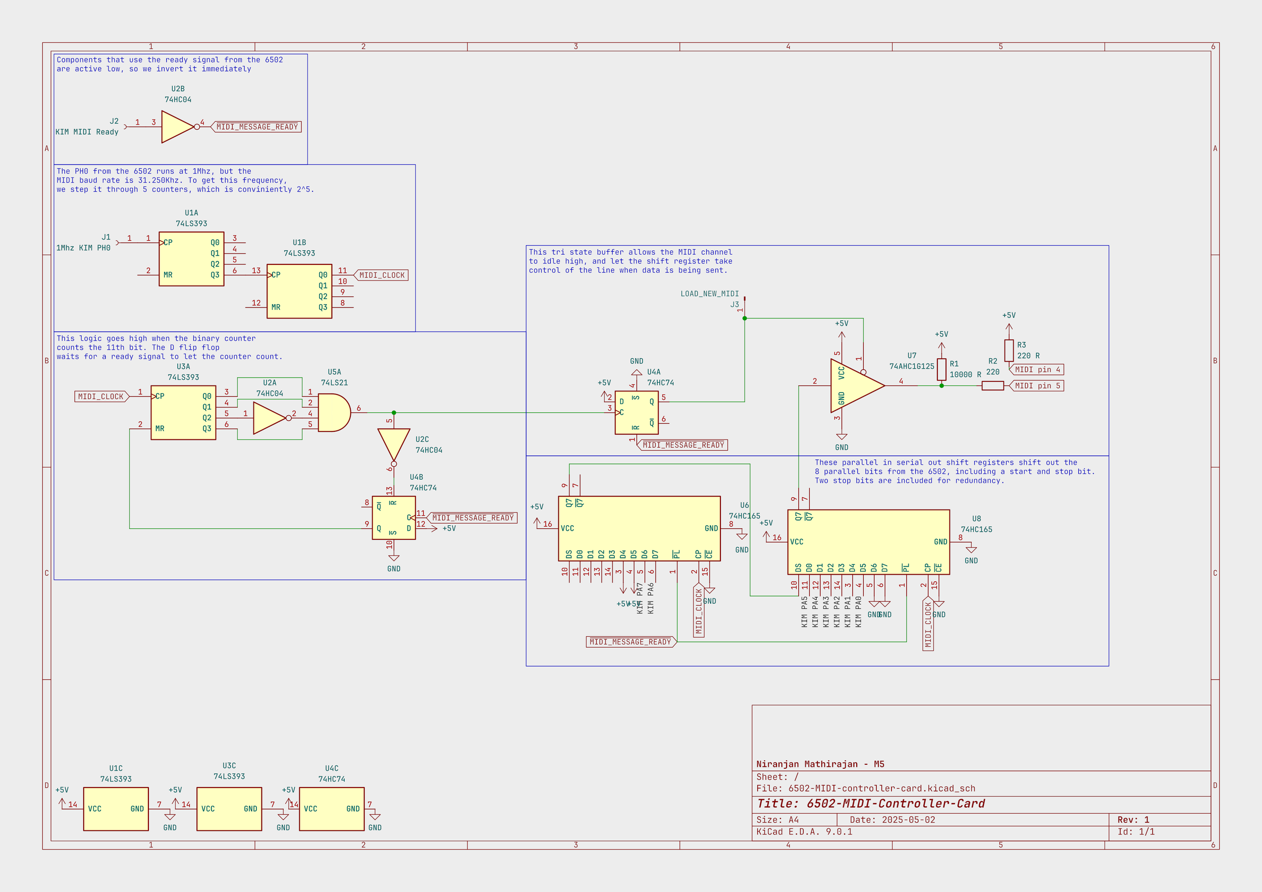
my circuit schematic, sketched in KiCad.
With this design, all the 6502 has to do is check if the MIDI line is idling, and if so, load 8 data bits into the shift registers, and pulse a ready signal, which tells the circuit to start sending the data.
The Circuit Walkthrough

The clock divider.
My circuit begins by taking a clock signal from the KIM. The 6502 runs at a 1Mhz clock signal, and the KIM exposes this signal for additional circuitry. I took this signal, then stepped it down using a 4 bit counter (U1) to 31.250Khz, which is the required baud rate of MIDI messages.
To make sure the 10 bits are sent correctly, I used a 4 bit counter (U3A) to count until the 11th clock signal, in which I stop the circuit, and tell the KIM to send a new MIDI message.

binary counter logic
The D flip flop waits for the ready signal from the KIM to allow the circuit to start counting. This way, the circuit idles until it’s ready to start sending data. The NOT and 4 input AND gate counts till 11, which is when the circuit should stop sending MIDI data.

These are the two shift registers which send the data out serially. They take in 8 inputs from the KIM’s memory mapped I/O ports, and pad the data bits with a start and a stop bit. I included a secondary stop bit, as a safety measure compensate for inconsistencies with the timing.

The output control logic
To finally control the output, I used a buffer which can switch between holding the output line high, and to the data being sent by the shift register. The buffer is controlled through the D flip flop, which will flip depending on the output from the 11th bit logic. This way, when the data is loaded, the buffer allows input from the shift registers, which send their 10 bits out. Once their done, which is also when the 11th bit triggers, the buffer switches back to holding the line at 5v.
The assembly code to use this program is quite simple. We use a writevalue subroutine, which just loads the stored values in predefined memory addresses to the memory mapped I/O port, and pulses a 1 in the outputInterrupt port. This tells the circuit it’s ready to send new data. After this, the wait_loop waits until the circuit sends back a signal, saying it’s ready to send new data.
To get the key mapping, I cross referenced this percussion set mapping, which seemed to be the standard for all MIDI compatible drum machines
write_value:
    LDA status,X
    STA outputData
    LDA #0b1
    STA outputInterrupt
    LDA #0b0
    STA outputInterrupt
    wait_loop:
        CMP outputInterrupt
        BEQ wait_loop
    RTS

write_note: ; sends 3 MIDI bytes according to the offset in X register (will modify A and X register)
    LDX #0x00
    JSR write_value
    LDX #0x01
    JSR write_value
    LDX #0x02
    JSR write_value
    RTS
I initially prototyped this project on a breadboard, in anticipation for the Circuits and Code event. This allowed me to connect to the KIM, which is where I was able to get the Clock signal, as well as all the inputs from the KIM.

Overall, this was an incredibly fun project, and hearing it make noise for the first time was awesome! I got incredibly familiar with tools like Logic Analyzers, and common debugging practices. In the future, I plan on designing this into a PCB, and maybe even understanding how the original Apple 2 computer (designed around the 6502 processor) reads programs, so I could have the actual Apple 2 play a song!