Accidentally Making a Transformer
Recently, I was trying to get the engine for my SDP team’s project kart to run now that we had a cooling system rigged up. However, I found that when I connected the battery, I immediately heard the injectors clicking. Since the engine was completely stopped, this should not have been happening, and the only cause could be a faulty RPM reading. After disabling the injectors and coils so that I could test safely, I found that the ghost RPM reading completely disappeared when I opened the throttle bodies. What gives?
To answer that question, it’s first important to understand exactly how an engine knows when to do what it does. There are three ways it’s usually done: optical sensors, hall-effect sensors and variable reluctance sensors. Both of these sensors are mounted next to a spinning disc on the crankshaft, and typically detect either a toothed wheel or a series of magnets with alternating polarity. An optical sensor will look for light passing through the gaps in the teeth, and generate a signal based on how fast the light is flashing. A hall-effect sensor will typically use either a magnetic wheel, or the sensor will have a magnet inside of it such that a moving piece of ferrous metal will change the magnetic field in a way the sensor can pick up. Both of these sensors output a digital signal, in that it looks like a square wave.
Variable reluctance sensors function a little differently, in that they use a coil of wire next to a magnet. When the toothed wheel passes by this, the metal moving into the magnetic field will cause the field to change. As Faraday’s Law of Induction states, this changing magnetic field will induce a current in the coil. This analog signal is much more fickle, since the voltage itself is induced by external magnetic fields and isn’t very strong.
I found out just how weak this signal is the hard way, when the engine started reading RPM that should not have been there. There was an error in the ECU, because the signal wasn’t the correct type for the trigger wheel I had in the engine. What told me just what was causing this issue was that the RPM signal went away when I moved the electronic throttle bodies. They draw quite a bit of current, so I knew that somehow, the current in those wires was inducing a current in the sensor wires.

The trigger wheel I designed for our engine, in a common 36-1 pattern
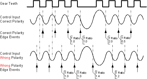
The signal that this wheel generates
Image source: https://mcs.woodward.com/content/motohawk/Documentation/MotoHawk2015bSP0/HTML/MotoHawk_topics/VRInterfacing.html
What I had inadvertently done was create a very bad transformer, that is one coil of wire that induces a current in another. To solve this, I needed to stop the noisy electromagnetic field from affecting the signal wires so much.
My solution to this was surprisingly easy: twisting the wires together and shielding them. Twisting the wires will ensure that any external fields will act upon each wire in a similar way, canceling out the interference. This also reduces the interference that current carrying wires will produce, as the fields produced by each wire will cancel each other out. Shielding the wires with a grounded sheath will protect the wires further by acting as a Faraday cage to reduce the electromagnetic interference that reaches the wires.
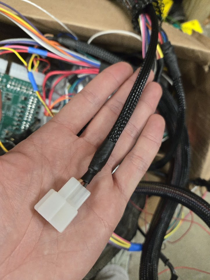
After twisting the wires together and adding a metal sheath that was properly grounded to the ECU, I wrapped it further in a nylon sheath to protect the other wires in the bundle from abrasion over time. The result is a properly nice-looking cable that’s significantly more protected from interference! While testing the engine after this fix, I had zero issues with the phantom signal.
Under the nylon sheath is a sleeve of braided copper running the length of the cable.
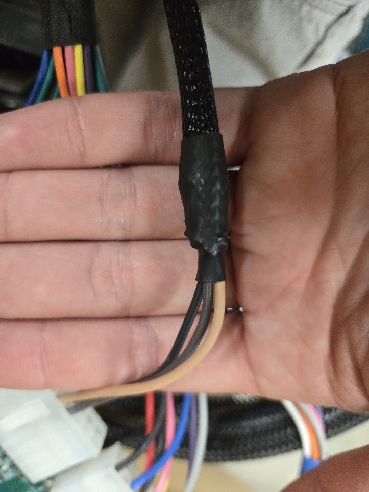
Two wires come in, three come out. The grounded shield helps protect the signal wires from interference that the other wires create.