Fused High-Side Driver
While working on my Senior Design Project, I found myself in need of a relay/fuse box to switch various electrical components. Rather than spend a few hours and a few dollars wiring and crimping everything by hand, I thought it would be a much better use of my time to spend far more effort and money to make a PCB using high quality components and connectors. While I’ve spent far longer on it that I initially expected, the benefit is that I can use high-current transistors as a reliable way of delivering current and can scale the design quite easily.
The layout I settled on for each driver looks something like this:
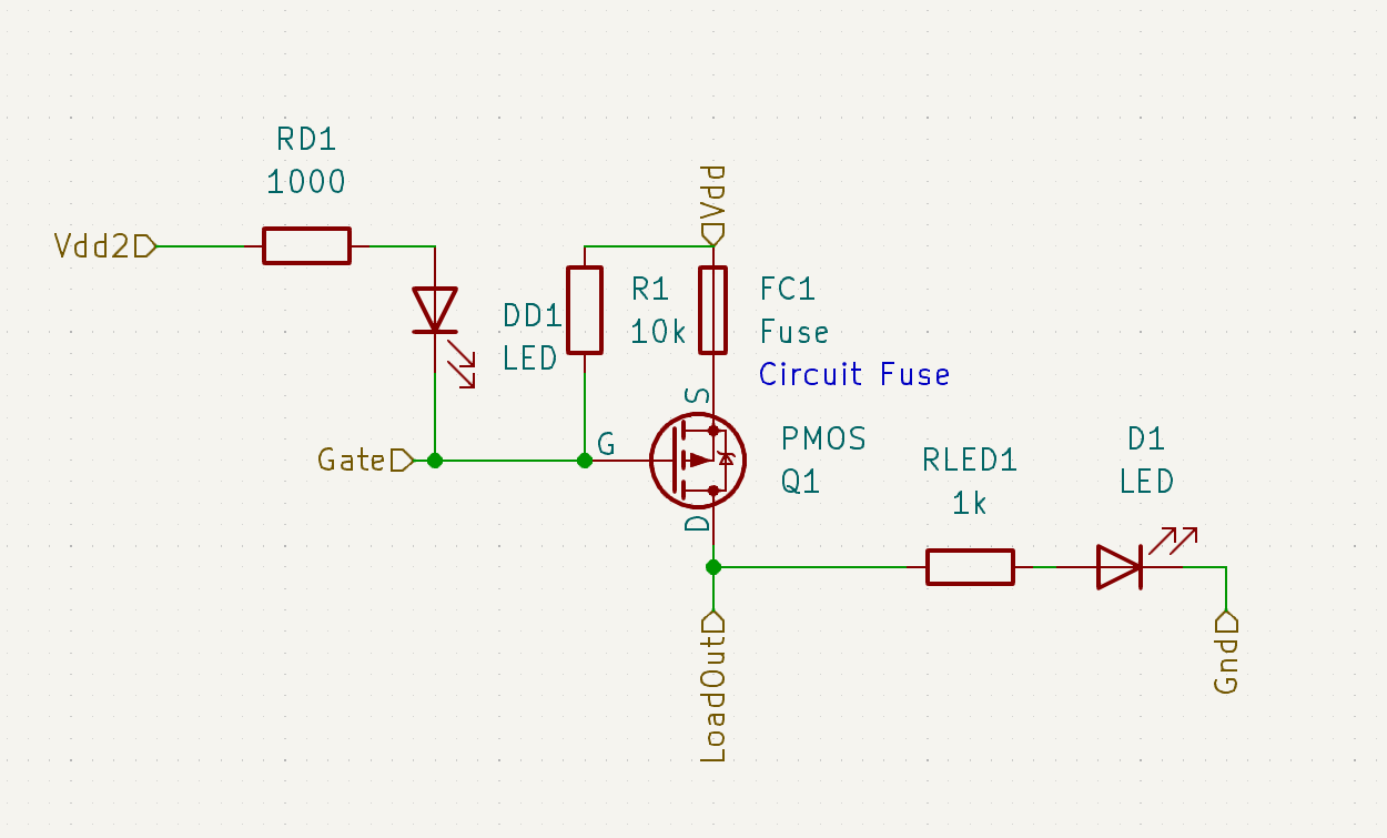
As the ECU I’m using to control the relays features several low-side outputs, I thought it would be best to use P-channel MOSFETS for their ability to switch current on the high side (as detailed in a previous blog post here). Because I chose to make everything on a PCB, I’m able to easily make a simple tileable design to house each “relay”. However, just a switch for each channel isn’t enough. As I plan on switching power directly from a battery capable of sourcing hundreds of amps, I need to fuse not only the battery input, but each circuit as well.
Since I’m already assembling a board, I figured it would be useful to have some LED indicators as well. One LED illuminates when the gate of the MOSFET is pulled low, i.e. when it receives the signal to turn on. The second LED will illuminate when the load is powered. This enables the user to find out if the fuse is blown at a glance.
Since it’s usually never good practice to order a PCB of a circuit which hasn’t been tested on a breadboard, I decided to build one of these drivers and test it out. In the video, the load is powered (green LED) when the gate of the MOSFET is pulled low (red LED). When the load is shorted to ground and too much current is allowed to flow, the fuse will pop. When the load is not receiving any power, the red LED will still illuminate, but the green one will not.
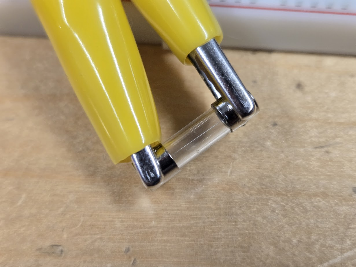
This fuse is alive… for now
When the switch is toggled, the power from the MOSFET is shorted to ground. The fuse blows, and the green LED indicates that the load is not receiving any power.
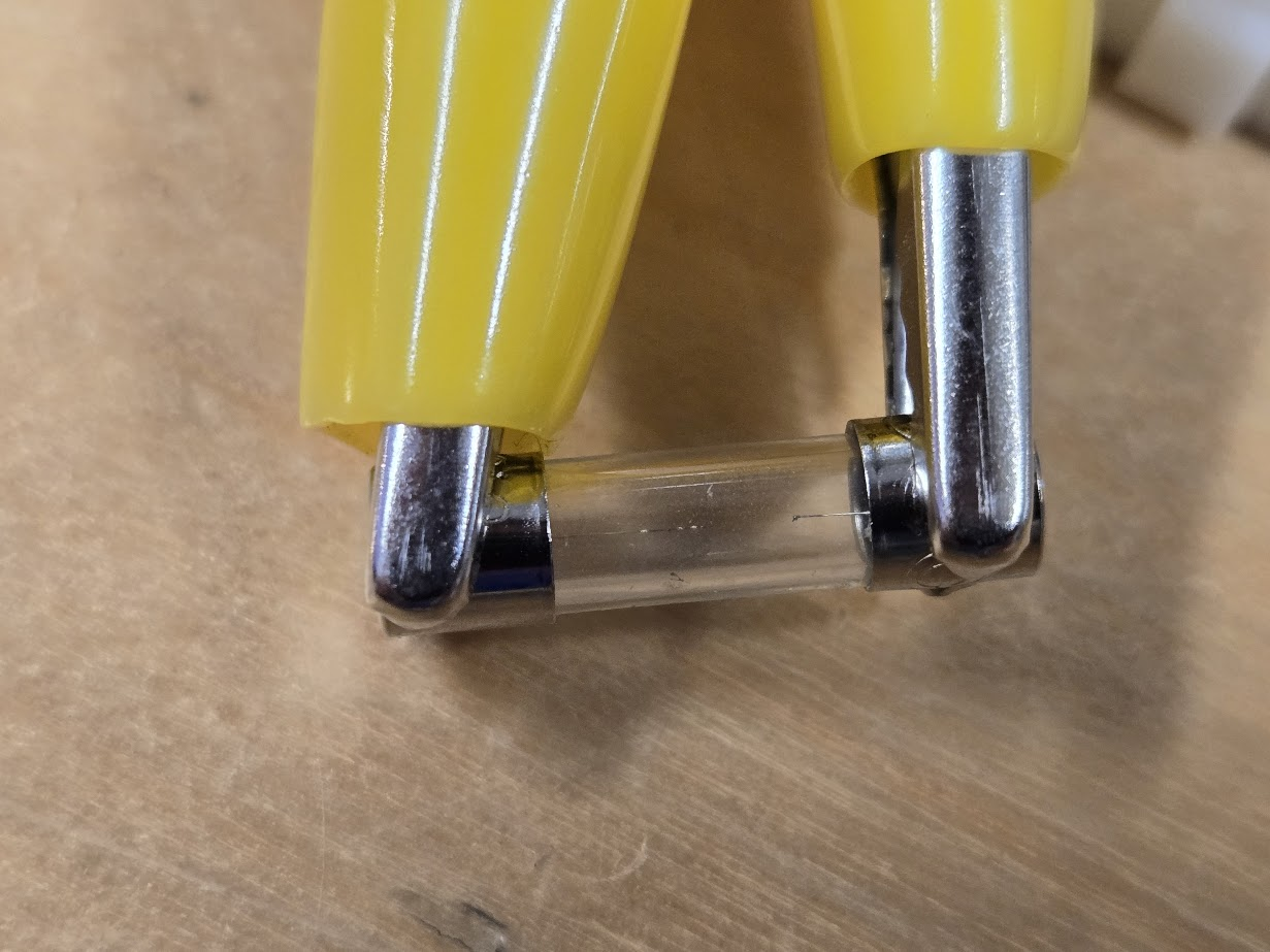
As the indicator suggests, the fuse is blown.
Now that I’ve made sure the circuit works as I expect, I’m ready to send off my PCB to get manufactured!
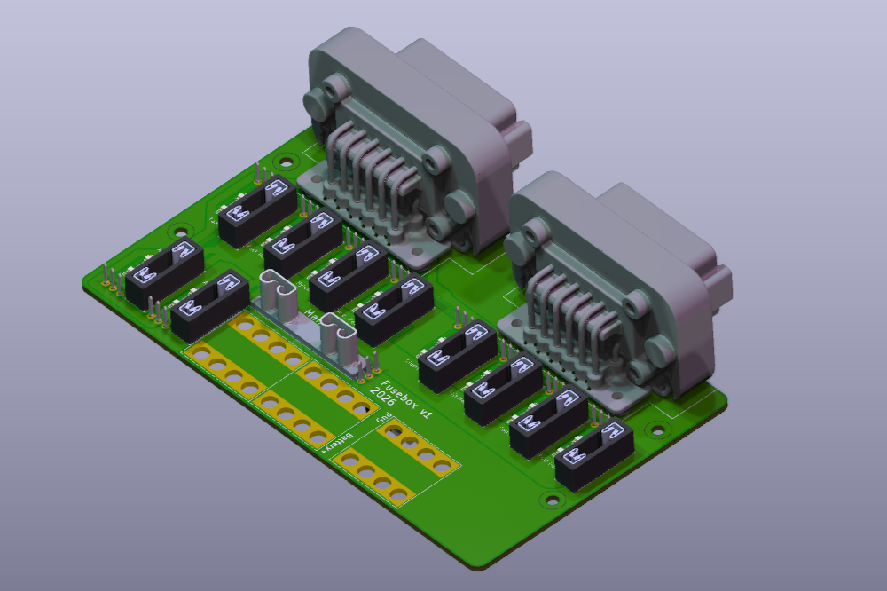
I saved 2 hours of crimping by spending 14 hours iterating on this board, but at least it looks neat