Current Limiter For the MassMileage Motor
Last week, the shaft of the motor broke and the engine team suspect that this is due to too much current going from the battery to the motor. So as one of the few EEs on the team, it is naturally my job to help them out with that.
The battery we have is 12V and we wanna bring the current down to around 1A, but we don’t have the actual measurements of the current that broke the motor shaft. Before building the actual circuit, I similated the circuit in falstad , a really useful circuit similation website: https://www.falstad.com/circuit/.
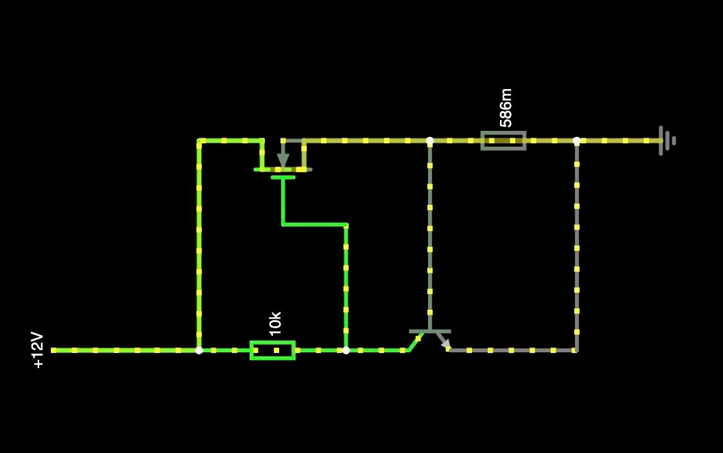
I set the two resistors as slidebars so I can tweak the values to see how the current is changing. Turns out, the 10k pull up resistor on the left changes the current very slightly and the sense resistor on the right is significantly more influencial. At about 0.586Ohm, the sense resistor would give us a nice 1A current.
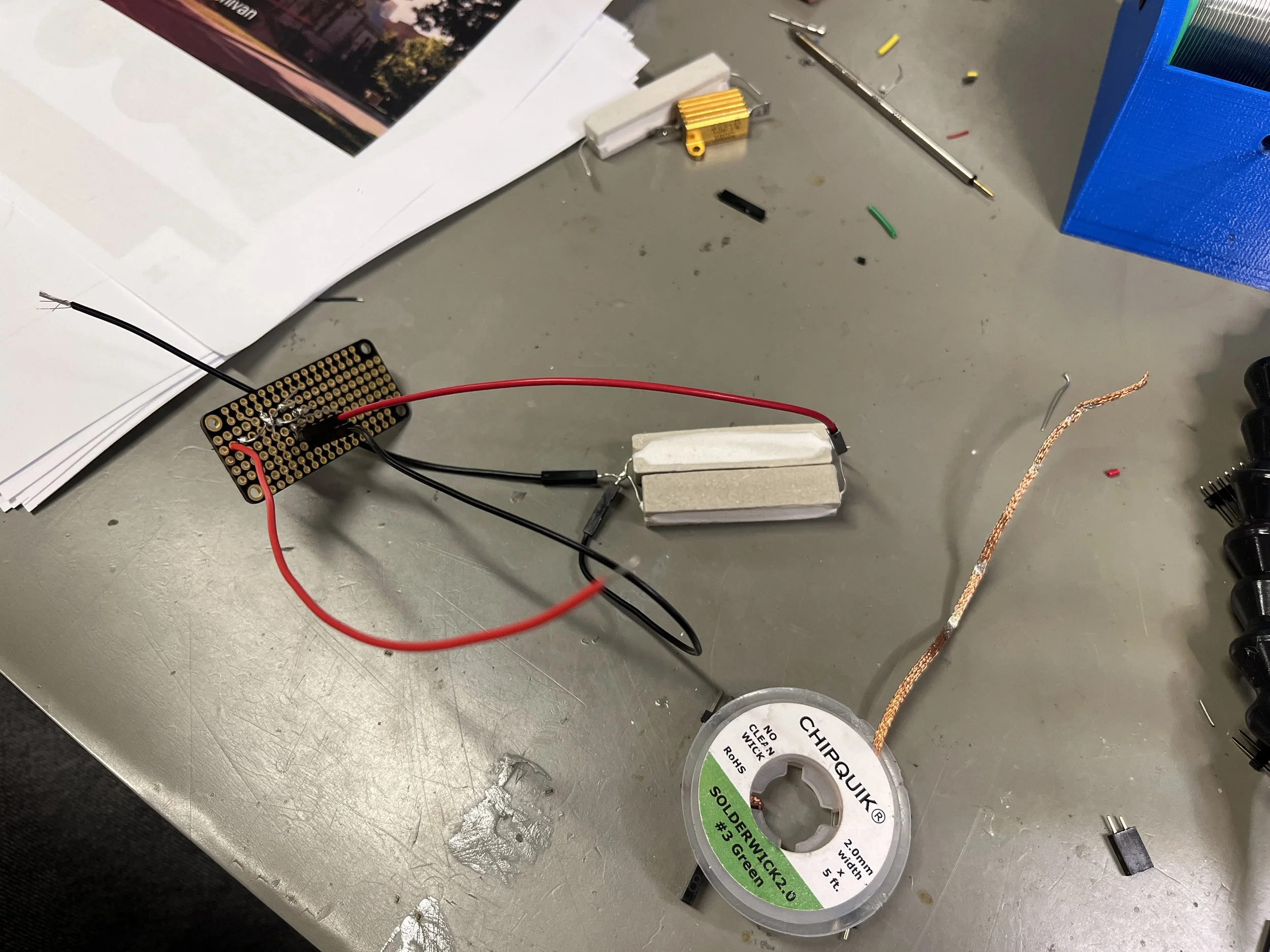
First version with messy wiring and very not ideal layout
I picked out some parts from the parts wall: 10kOhm metal film resistor, a BC548 NPN transistor, a STP30NF20 N-Channel MOSFET, and two 1Ohm power resistors(because they are 10W and in series could make 0.5Ohm). Marie Elster, my team member worked on this circuit with me. We started off thinking it wasn’t gonna be too hard to layout since it’s only a couple of components but it requires more connection than we expected. We also wired sth wrong so we had to redo the whole thing.
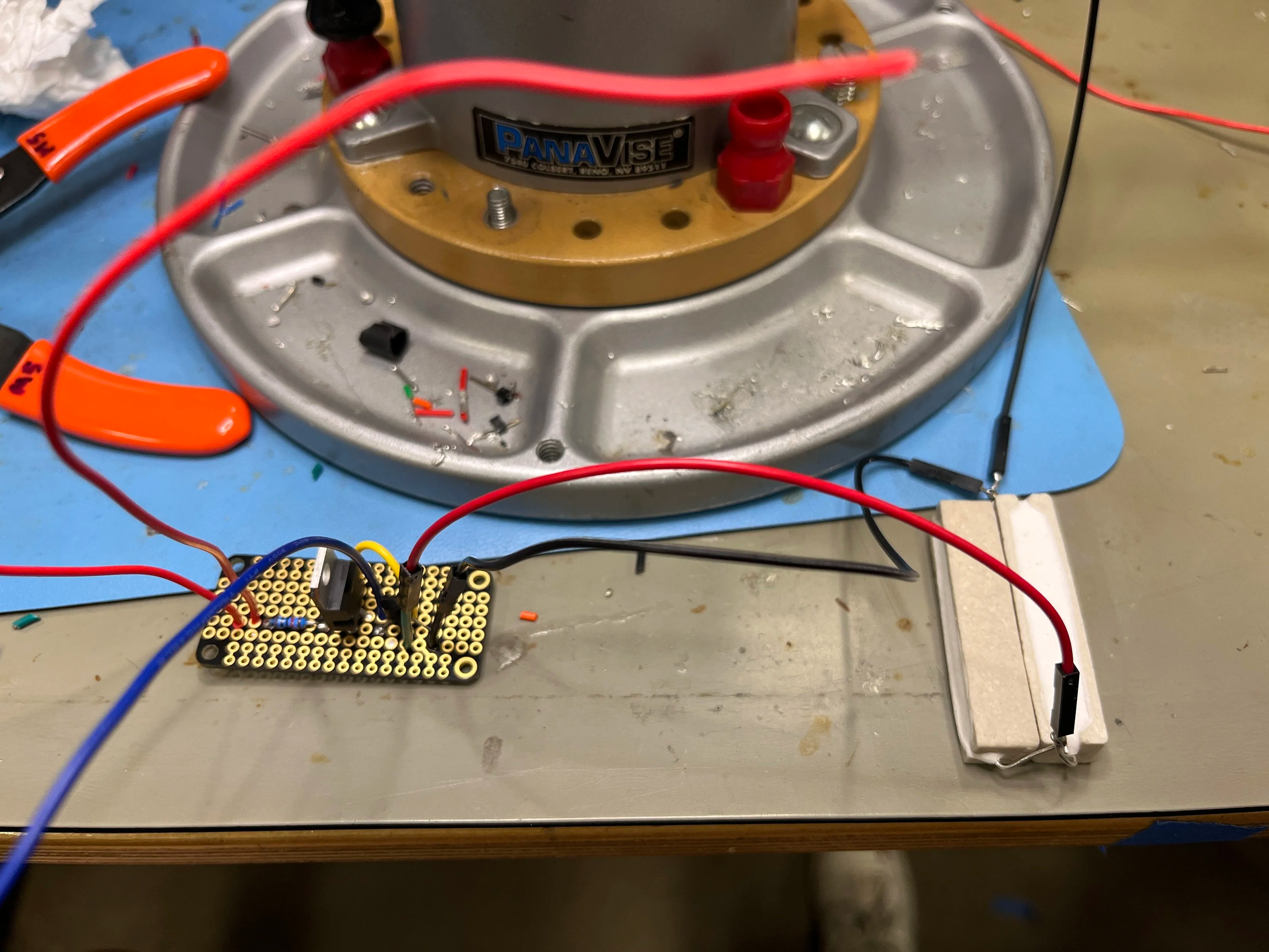
front view
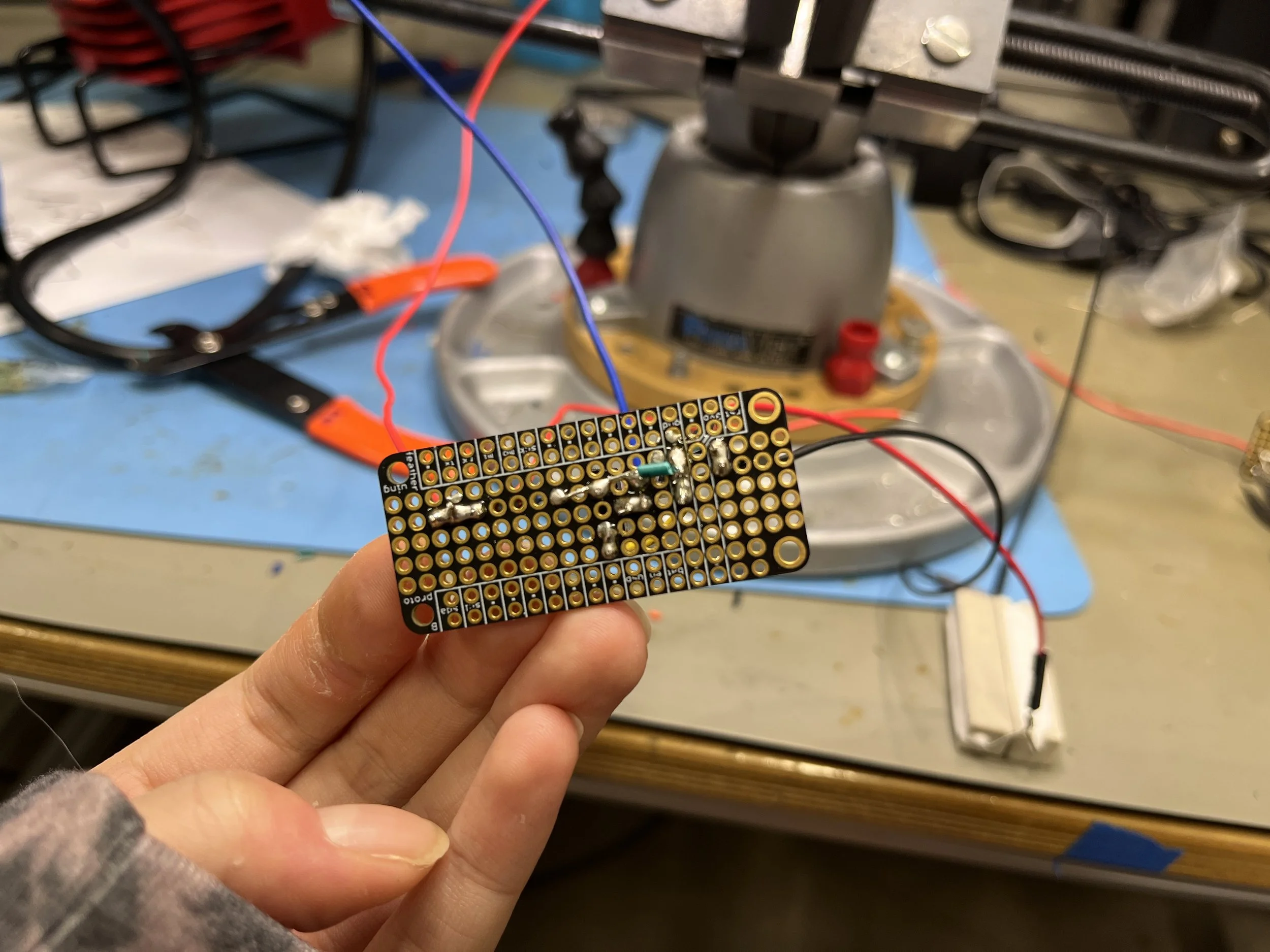
back view (beautiful soldering job by me)
The blue wire and one of the red wires goes to the motor, the black wire and the other red one goes to the battery. Unfortunately when we handed this over to the engine team they already decided to use the old engine, but this will still be in use after competition!